Build directions
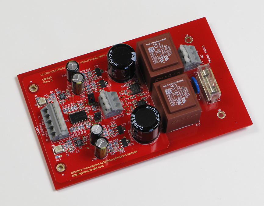
Click on the picture to see a larger view of the pcb.
This design is very easy to build. You can of course solder everything and then apply voltage but maybe it doesn't hurt to be a little cautious. You should start with all low SMD parts except for the output power amp and the opamp because it's harder to solder the SMD parts when you have big parts in the way. For this solder job I recommend a good pair of tweezers. I use a type especially made for SMD. With this tweezer I get a very good grip. You must also have a soldering iron with a small tip but at least 50 watts in order to be able to solder the buffer which requires lot's of heat.
Start with all low SMD parts except for the output power amp and the opamp.
- Resistors
Transistors
Trim pot (if you use it)
Capacitors, not the hole mounted ones
Rectifier bridges, at last - Then continue with the high electrolytic caps, mount all caps
- Connectors
- Jumpers
- Transformers
- Varistor
Apply voltage, 230 volts AC. Check that the regulators give the expected voltage, +- 12 volts. Disconnect the power and see to that the voltage is zero when you continue the soldering.
Continue with the opamp and output power amp.
- Opamp.
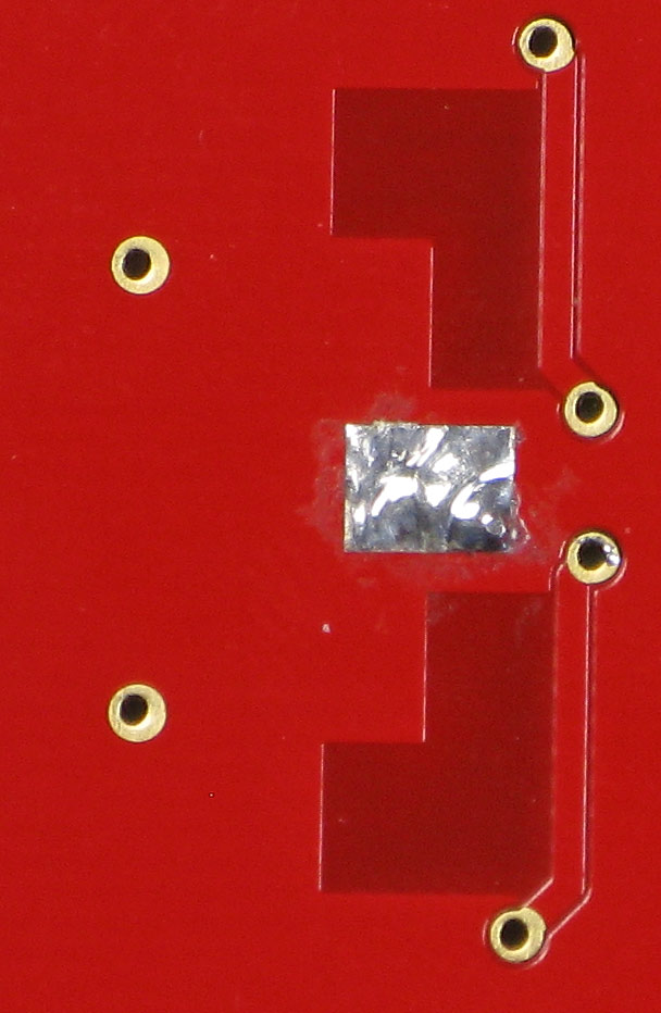
- Output power amp. This part needs to be soldered into the large pad on the pcb. To do this you must use lot's of heat. If you have two soldering irons, use both at the same time. The buffer gets it's cooling via this pad so it's important that the buffer is very good soldered. When I soldered this IC, it turned out not to be so difficult. Solder the pins as usual. Then solder the backside. Turn up the soldering iron to max temperature, like 450 deg C in my case. Warm and add tin and continue to warm for 10-20 seconds or so. Notice how the tin gets sucked up through the via holes. You can "burn" quite a lot and the upper side won't melt.
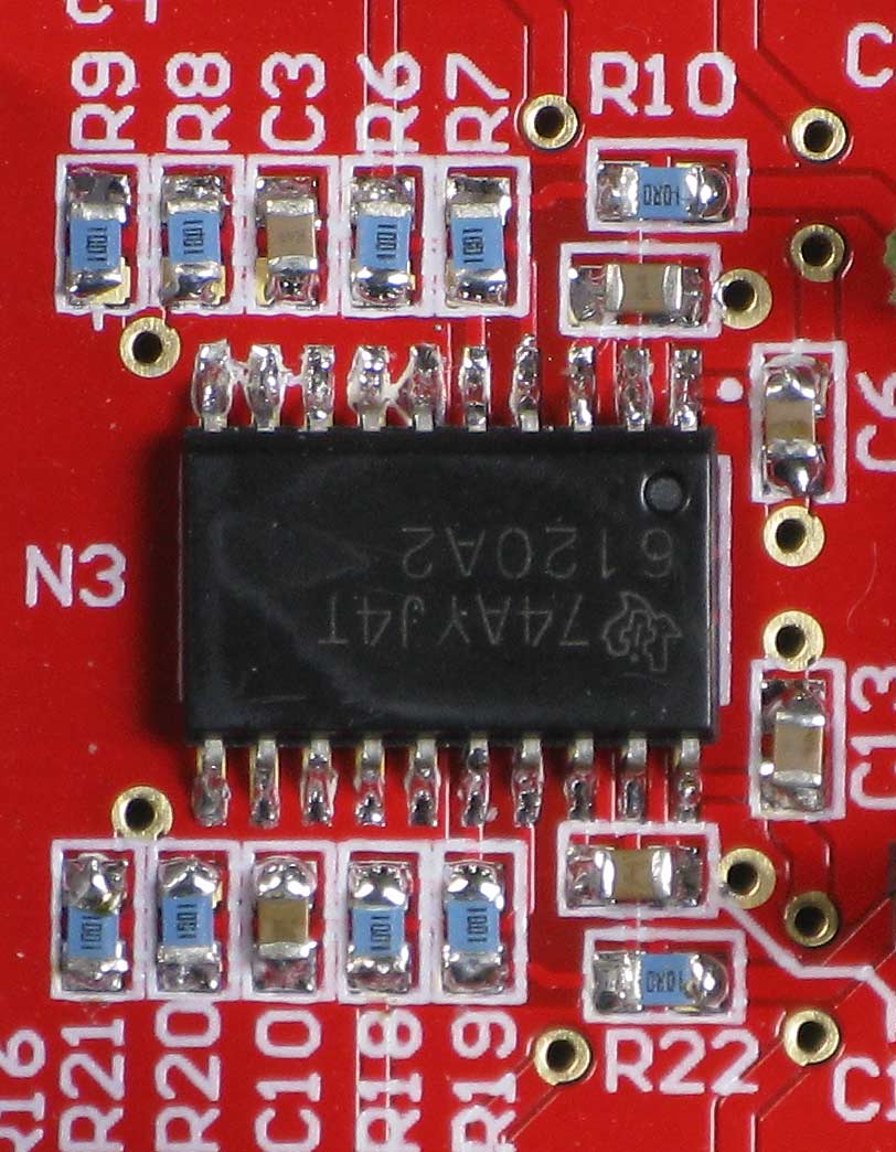
Click on the pictures to see a larger view of the pcb.
Detail of the TPA6120 and how it's soldered. Notice the 18 vias under the IC which serves as heat transport.
Check the finished amp
Apply voltage again and check the output voltage. Measure the DC voltage at the output. It should be the specified offset voltage (see datasheet) and times the gain, 4 in this case. I got 78 uV(!) for AD8610 and 2 and 10 mV for the TPA6120 at the amp outputs. 10 mV is OK and won't harm the headphones.
The whole amp is ready.
Test if you want the different drive modes. It is safe to change modes when voltage and input signal is applied. You won't even hear a click.
Good luck and happy listening.


