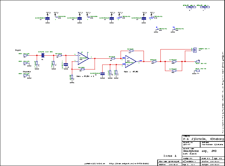
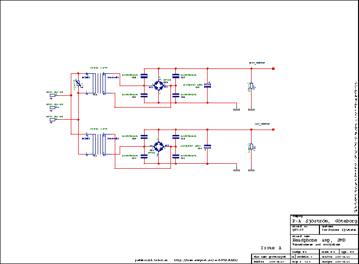
The schematics, page 1 and 2.
Click on the picture to get a larger view. The picture shows the schematics of the amp. Of course you can't use it for anything except for an overview. Please download the pdf-file instead if you want to see the details.
The text is for the left channel.
The main part is a power amp, the TPA6120, IC3. The TPA6120 is a new headphone amp IC with extra good driving capability of 700 mA which will be sufficient for all headphones on the market. The TPA6120 is of a current feedback topology and this makes the inputs a bit unusual. The input bias currents are around 12 µA which more or less means that you must use a buffer in front of the TPA6120. This IC is designed to be used with low impedance signal sources so in order to avoid problems I have chosen to let an AD8610, IC1 feed the TPA6120.
Inverting mode for the TPA6120
The TPA6120 runs in inverting mode just because this will reduce the distortion by a factor of 10. This means that this design will invert the signal. Some people have problems with that but the only way to circumvent this is to use Sennheiser headphones with separate cables. Sorry believers for the absolute phase, this is not a product for you. Still it isn't totally impossible to change the amp to a non-inverting one but it requires a bit handiness. I leave this to those who are mighty for the task.
The input buffer
This design needs an input buffer because of the rather high input bias currents of the TPA6120. I have chosen AD8610 just because I like it. Any good single SO08 opamp will do here.
The gain
The total gain is determined by R4 and R5. Gain = R5/R4 + 1. Low values of these resistors is important if you want low noise.
The output has R10 and R11 in parallel with R12 this serves to purposes. The first one, R10 is to let the TPA6120 feel a pure resistive high frequency load or simply isolate the amp from capacitive load. R11 and R12 is common practice to interface normal headphones. Without these resistors it's very easy to damage low impedance headphones but if you have full control over the situation, omit those resistors, use the jumper J1. I should mention that many headphones are designed to be driven from a certain source impedance. Some people claim that this impedance is 120 ohms. Test this if you want to optimize the listening experience.
The input filter
The input filter is very universal. You should have a lowpass filter, R3 and C2, but if you don't have any RFI trouble at all, it's not necessary, just replace the R3 with a jumper and omit C2. DC blocking capacitor may be necessary but check with your signal source first. The whole amp is DC connected so you must ensure that you haven't got any DC in your signal. The resistor R2 creates a DC path for the inputs of the opamp, otherwise it won't work. R1 is a pulldown resistor so the input coupling capacitor won't pick up any charges when the amp is unconnected. A charged capacitor can create a nasty spike at the output when something is connected to input.
The output power amp
The output power amp is the TPA6120 and is a current feedback type. I gather it's similar to my QRV-06. I recommend some reading in the datasheet of this very exciting IC. It's obvious that this extremely fast IC not is suited for anything else than a high quality printed circuit board. This pcb which I have made has double groundplanes, both to ensure good HF properites and also goos cooling.
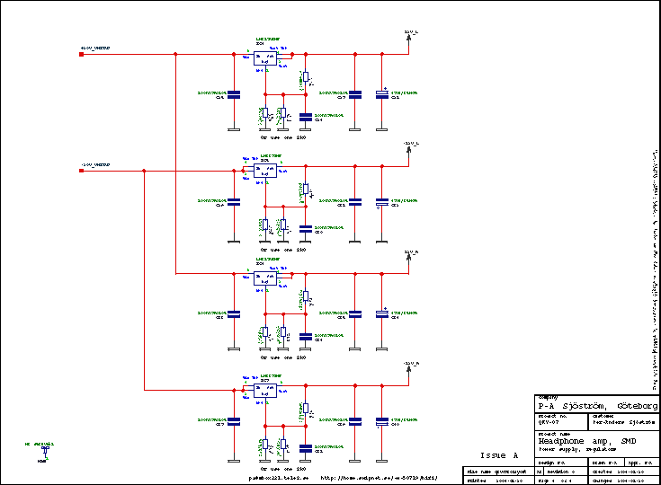
The schematics, page 3
The schematics, page 4
Click on the picture to get a larger view. The picture shows the schematics of the amp. Of course you can't use it for anything except for an overview. Please download the pdf-file instead if you want to see the details.
The power supply is not very exotic, rather straight forward. It's designed to use two transformers, one for the positive voltage and the other one for the negative. I have also used the option to have separate regulators for each channel. It may add some positive effects but I don't know how much. The TPA6120 has an option for separate power connections so why don't use it? Those regulators are cheap and it certainly can't hurt.
The regulators are cooled by the groundplane and of a copper area on the upper side. Practical tests have shown that it works pretty good. The amp is warm, not hot in hard usage.
R25, R26 are bleeder resistors. The regulators won't discharge the capacitors completely when the have reached the voltage of 0,6 V. The resistor creates a clean start at power up.
C15-C18 are for reducing EMI caused by diode switching.
The transformers are short circuit proof by design, therefore you don't need fuses.
R39 is for transient suppression.


