The Gainclone Story
From Wikipedia, the free encyclopedia
http://en.wikipedia.org/wiki/Gainclone
The arcticle about the Gainclone became in the end heavily censored/edited, possibly good but I think it should be mentioned about the Gainclone pcb's available on the net. Therefore I have taken a snapshot of this article and here write after my own will. Some of this arcticle is my work already.
The arctile below is based of the revision as of 15:57, 11 January 2007
Gainclone or chipamp is a term commonly used to describe a type of audio amplifier made by do-it-yourselfers, or individuals interested in DIY audio. It is a design based on high-power integrated circuits, particularly the LM3875 from National Semiconductor. The Gainclone is probably the most commonly-built and well-known amplifier project amongst hobbyists. It is simple to build and involves only a few readily-accessible, inexpensive parts. As an amplifier it is highly-regarded by many in the DIY community.
Contents |
Background
In 1999, 47 Labs introduced the Gaincard amplifier. The Gaincard shook the audiophile community with its unconventional design. It had fewer parts, less capacitance and simpler construction than virtually anything preceding it, and relied on a 56 watt chip for amplification, the National Semiconductor LM3875. These construction techniques went against the accepted wisdom of the time, which favored large power supplies and discrete amplification. This Gaincard was estimated to cost less than 100 USD in parts, but it sold for 3300 USD with its small power supply. Controversy ensued after a number of positive reviews.
Modern Usage
The DIY community started building replicas or "clones" of the Gaincard using integrated circuits from National Semiconductor and other manufacturers in an attempt to see if good sound could be obtained, thereby the term: "gainclone". The name was first coined by a poster called "triodont" on the popular Audio Asylum board (ca. 1999; [2] [3]). Triodont tried to replicate the 47 Labs Gaincard amplifier (for his own personal use) and reported about it on the internet forum. Various modifications or improvements (depending on how you look at it) have been made to the original application circuit found in National's design notes since then. The simple circuits were easy to make and some started offering printed circuit boards and kits to make construction even easier.
The design concept has expanded and become rapidly more popular over the last few years as the simplicity of the design and availability of parts make it within reach of even a novice constructor. Now, the term "Gainclone" could apply to almost any amplifier based on a power integrated circuit of some type, from any manufacturer. In fact, the more common term today for such amplifiers is "chipamp" rather than "Gainclone", as the desire to copy the Gaincard has given way to broader attempts at using IC amplifiers.
Controversy over these Gainclones still exists, and variations have spawned. There are hundreds of web sites with examples, kits, circuits, and descriptions of the Gainclone amplifier.
Typical Characteristics

- A power opamp or audio opamp chip such as the National Semiconductor LM1875, LM3875, LM3886, or LM4780
- A very physically short feedback loop
- Miniaturised construction with short path lengths throughout the circuit
- Minimal extra components, usually of high quality
- Small power supply filter capacitors (often around 1000uF)
- Can be made using point-to-point construction rather than a PCB
- The power supply is often built in a separate chassis from the amplifier
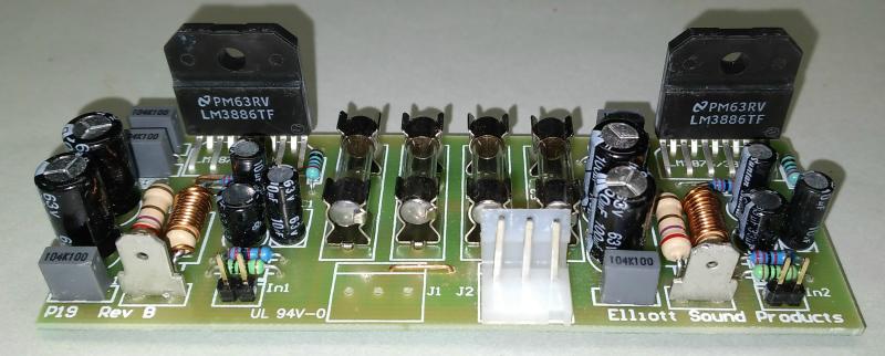
The National Semiconductor chips come in two versions. The "T" model is not insulated and has better heat transfer properties but it needs insulation when mounted on a heatsink. The "TF" model as in the picture is covered in plastic, and thus insulated, but it has less efficient heat transfer properties which means it can't run continuously at full power. The "T" model is recommended for heavy duty applications.
The Sound
Most designs are very effective and produce extremely high quality sound, even though some audiophiles consider chip-based amplifiers to be inferior to their discrete counterparts. Many others, however, are astonished by what these amplifiers are capable of. The chips have been carefully designed to incorporate a number of desirable features, including excellent power supply rejection ratio, fast response and accurate bias current.
The original product, Gaincard
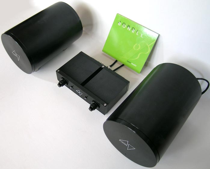
This is the original product with the amplifier in the middle and searate power supplies for each channel on the sides. Photo 6moons

Detail of the Gaincard, front panel. Photo 6moons
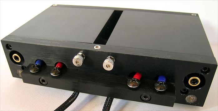
The backside of the Gaincard. Notice the plugged screws in the lower corners. Why? Photo 6moons
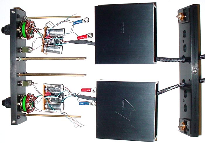
The Gaincard taken apart. Two things to notice. 1 The wire size. 2 The pcb style. The cheapest phenolic paper. Photo 6moons
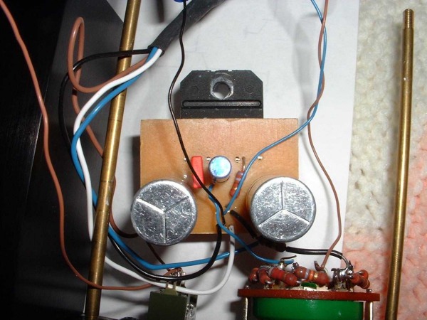
The pcb in a high-end product. Nothing to brag about. The pcb is probably made by hand. Photo 6moons
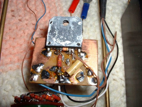
The pattern is probably done using paint and then etched. This looks chocked the diy community. Photo 6moons
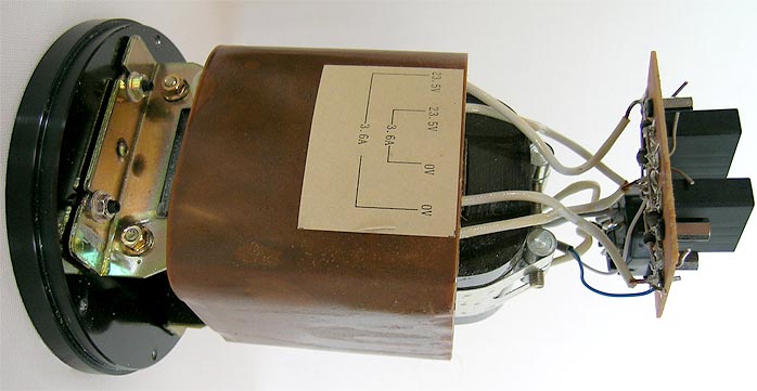
The power supply would probably not been approved by European standards. Photo 6moons
Comparisons and Attempts to Duplicate the Gaincard
Although the inspiration for the Gainclone comes from the Gaincard amplifier, not many try to copy the insides because the internal layout of the amp is a bit odd to say the least.
There was a long lasting debate going on in several DIY forums whether or not the two images show the real Gaincard or a clone. The US importers denied that the images showed the innards of their product, but a more recent image (below left), given to the 6moons editor by the US importers, shows essentially the same components. The Gaincard images were eventually analyzed in detail and converted into a schematic by Mick Feuerbacher, which has led to a consistent picture.
The modern Gainclone
The most well-known Gainclone implementation is the one from Brian Bell and Peter Daniel. The design is a collaborative effort from members of www.diyaudio.com, the world's largest DIY audio forum.
From time to time the PCB has been made available through a groupbuy at diyaudio, but PCBs and kits can also be obtained from www.chipamp.com (closed down), www.audiosector.com and www.madaboutsound.com. There are other PCBs and kits available, with a few from commercial sources, but most come from hobbyists.
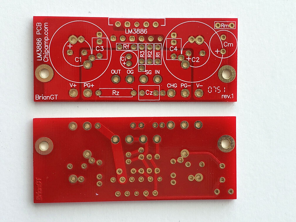
This is the orginal Gainclone pcb designed by Brian Bell (BrianGT) with help from the diy audio community including Per-Anders Sjöström which help to tune the grounding tracks. It's exptremely important with the grounding if the lowest distortion possible is wanted.
Another example of a modern Gainclone designed by Rod Elliott. Photo borrowed from him.
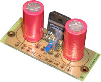
Gainclone printed circuit board of Brian Bell and Peter Daniel. This one was sold by Audio Sector. The only difference compared to the original is the colour of the solder mask.
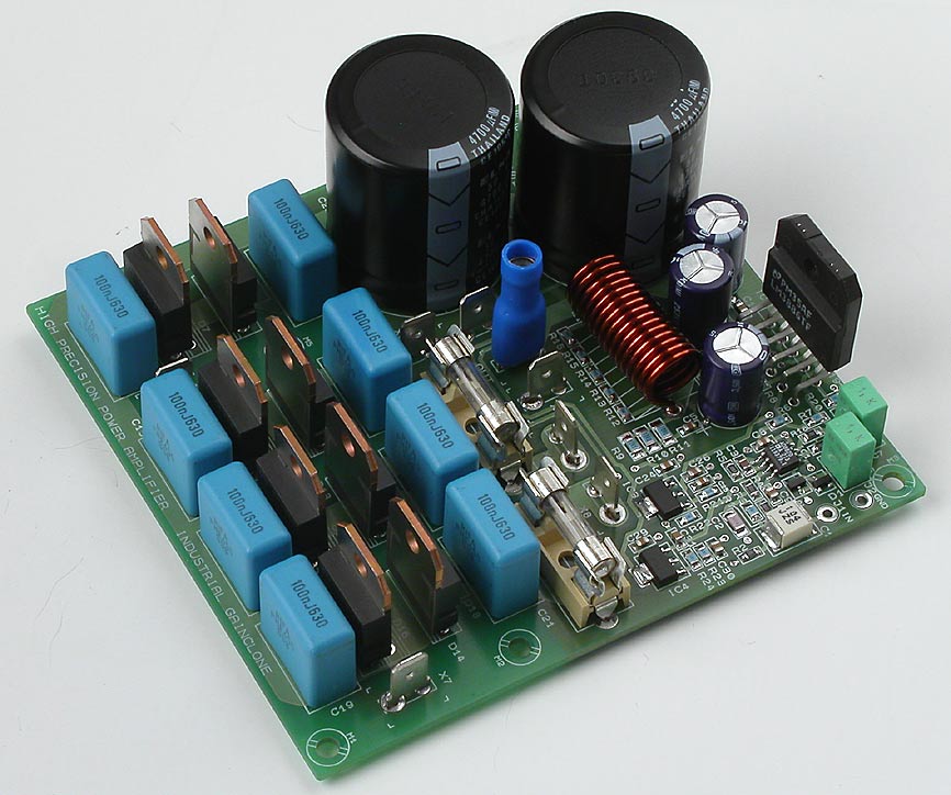
Gainclone designed by Per-Anders Sjöström. This design contains the power supply plus DC-servo.
Links
- Forums

