RFB-03 - The high current ultra fast rectifier bridge
Click on the picture to get a larger view.
Interesting features
- Possible to use fast diodes
- Four layer printed circuit board
- High current pcb, thick copper traces
- 4 x 70 um copper thickness (70 um = 2 oz.)
- Pure gold on the pads and all other exposed copper surfaces
- "Snubberized", each diodes has snubbers
- Can take just about any diode, TO220, TO218 and TO247
- Possible to mount the diodes on a flat surface
Why did I design this?
Some people feel that they need a faster rectifier bridge than the normal 1-50 µs in 50/60 Hz applications. I have seen on the internet that there are few products out there which can take max 2-3 A because the don't have any cooling arrangements.
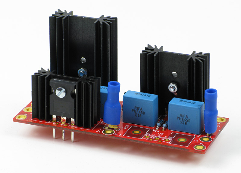
My design can take a lot more current because I have four heatsinks, one for each diode but you can also attach all four diodes to a plane heatsink. If the heatsink is large enough this rectifier bridge can handle as much current as the max rating of the diodes. The chosen MUR3020PT or MUR3020WT can handle 30 A continuously. The new revision of pcb can now also handle TO220 diodes. MUR820 (200V, 25 ns) and MUR860 (600V, 45 ns IR, 25 ns ON-Semi) seem to be good choices. I have chosen MUR820 because ELFA has it.
Two manufactures of diodes can be found here:
The heatsinks can be chosen after demand of cooling and they have a standard profile which can be obtained from Aavid, Fischer, Redpoint and Austerlitz. The heatsinks at the picture are 25 mm (1") high but you can get these in 38 mm (1.5") or 50 mm (2"). If you want to use the diodes at it's maximum you must use an even bigger heatsink. Just bend the diode pins in 90 degrees angle and attach the diodes to a heatsink with a plane surface. Since the diodes are have fully symmetrical pinout you can mount them on the solderside or the component side.
The schematic
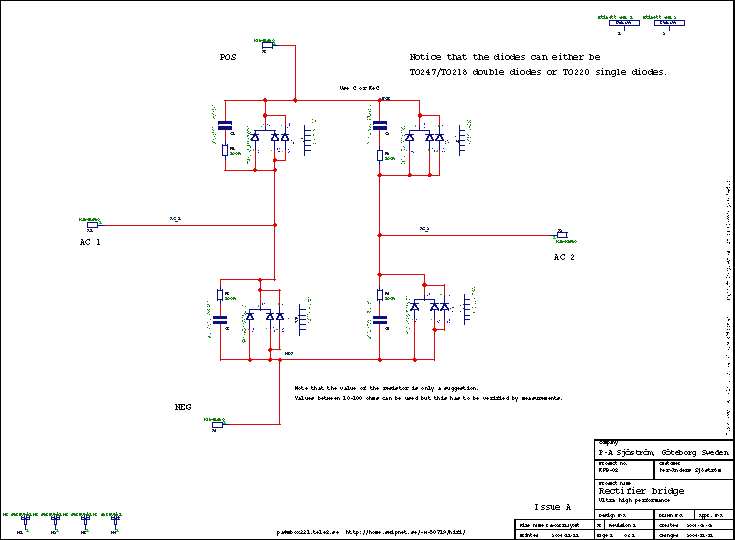
The circuit
The rectifier bridge is built by four ultra fast recovery diodes plus four heavy duty polypropulene capacitors PHE450 from the famous swedish company EVOX-RIFA. As an option you can choose to have only a capacitor or a capacitor plus a resistor. The values can go from 1-100 nF and 1-100 ohms and to really determine the exact value you must have spectrum analyzer which no DIY'er have I suppose. 1 ohms and 100 nF is a good start I think. You don't have to use the type of capacitor I have suggested. The pcb has holes for almost any type with pin spacing, 0.2, 0.25, 0.3, 0.35, 0.4, 0.45, 0.5, 0.55 and 0.6"inch, from 5 to 15 mm.
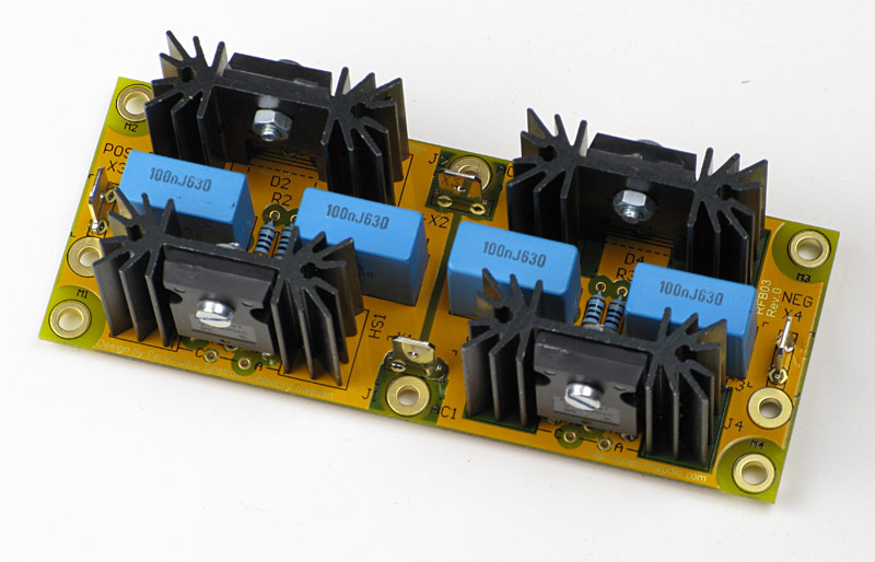
Top view of the RFB-03, showing the yellow prototype.
Virtually any diode, especially if they have TO247 or TO218 case, fits. You can even use regular round ones. MUR3020 (200V, 35 ns) and MUR3060 (600V, 60 ns), MUR820 (200V, 25 ns) and MUR860 (600V, 45 ns IR, 25 ns ON-Semi) seem to be good choices.
Two manufactures of diodes can be found here:
If you plan to use this bridge in a preamp, you probably won't need any heatsinks. If you plan to use this bridge in a heavy duty application you must use heat compound between the diode and the heatsink. This compound is usually white and I recommend that you to use a silicone free product because the silicone has the tendency to creep all over the place and collect dust.
You connect the bridge with ordinary lug connectors but you can also use cables with an area of 6-10 square millimeters using the big holes beside the lug.
As a general rule for this project, use any component, audiophilic or not. As long as it's fits for the application it's OK to use it.
Build directions
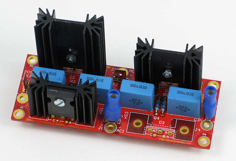
It's really easy to build this bridge.
Suitable building order
- Resistors
- Capacitors
- Spade connectors
- Mount the diode to the heatsink. As you can see you can have different sizes of the heatsink, 25 mm (1"), 37 mm (1.5") or 50 mm (2 ").
- Mount the diode-heatsink package. For heavy duty applictions it could be wise to use heat compound between the diode and the heatsink.
You don't need any insulation because the heatsinks aren't connected to anything else than the cathode of the diode.
Mounting the heatsinks
Solder the heatsink with a very small drop of tin, just so it won't fall off. Then solder the diode. When the whole bridge is finished and tested you may solder the heatsinks a little bit better. This is just a precaution if you want to remove the heatsinks of some reason before you are completely finished. Once you have soldered them in they will be impossible to remove without damaging the pcb.
Soldering
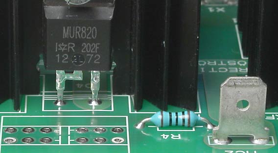
The picture shows RFB01 but the problem is the same with RFB03 and even more accentuated since there is so much copper. Some parts are demanding in terms of heat. The pcb has thick copper which cools very effectively. Therefore you must "fire up" some pads. If you have a temperature controlled soldering iron turn up the temperature to max, maybe 450 deg C! Stop warming when the tin has start to flow up on the component side. See the picture above. Notice also that the lug (at the picture) had a thick oxide layer. The soldering joint isn't perfect. The tin hasn't wet the surface of the lug but still, the quality is fair.
Test

To be extra sure test this bridge with low voltage and small currents. Use max 24 VAC and 1-2.2 kohms load. Measure that you get correct voltage. 24 VAC will generate 24/1.11 = 21.6 V if you don't have any smoothing caps. If you don't get fullwave rectification you will get only 10.8 V. Don't use any smoothing capacitors for this first test because you won't be able to notice if you have full or halfwave rectification.
Connect this ultra high performance rectifier bridge in your amp now and good luck. You won't be disappointed.
Technical data
| MUR3020PT | Unit | ||
| Peak repetitive reverse voltage: | 200 | Volts | |
| Average rectified forward current: | 30 | Amps | |
| Peak rectified forward current: | 60 | Amps | |
| Non-repetitive peak rectified forward current: | 200 | Amps | |
| Maximum reverse recovery time: | 35 | ns | |
| Dimensions: | 43 (1.7") x 109 (4.3") | mm (inch) |
For complete data, please read the datasheet. Different brands aren't 100% identical in performance. Any TO247 or TO218 diode with common cathode will fit or a regular single TO220 diode.
How to change the rectifier bridge into heavy duty operation

Tweaking the RFB-03 rectifier bridge
The high-end audio designer Sigurd Ruschkowski has thought a bit how to tweak this rectifier bridge into higher levels of performance. If you wonder about anything, please ask Mr. Ruschkowski.
RFB-03's in dual bridge setup and with AC filter capacitors
Read more how to tweak RFB02 and RFB03.
