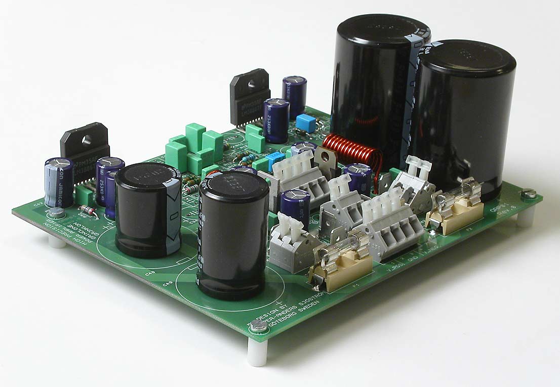
Build inverting input buffers
The inverting input buffers
R1, R4, R5, C1, C2, C4, wire in C5, C7, IC1 or IC2. Use IC sockets only if you want to change the opamps easy for experimenting purposes but if you are pretty sure of the opamp choice, skip the sockets. If you do want to use these use high quality sockets with "tulip" contacts and goldplated (round holes). Avoid sockets with flat contact springs for permanent use. They have less contact pressure and may cause you trouble especially if you have very small currents which the opamp inputs have. Don't save any money on sockets. Use the best, but best is to avoid them completely.
R23, R26, R27, C28, wire in C29, C31.
Apply voltage, +20-42 V DC and -20 to 42 V DC. Check the output offset voltage. Less than 2 mV is acceptable. Measure with a voltmeter at pin 1 and pin 7 at IC1 or IC2.
If the offset voltages are OK, apply some sinus signal or music signal. Use an oscilloscope or headphones with 100-560 ohms in series (just to protect the headphones) and observe superb sound quality. If all work so far (good!) then start with the main IC, the LM3886.

