The design
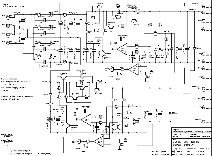
Click on the picture to get a larger view.
The picture shows page 1 of the schematic. Of course you can't use it for anything except for an overview. Please download the pdf-file instead if you want to see the details.
The design is rather unconventional but not very complicated if the different sections are identified. It has similarities with the Jung Super Regulator (as it has been called lately by the diy people) but was designed long before Walter Jung published an article in Audio Amateur, issue 1 and 2, 1995.
The major difference is that the opamp gets it's power from the unstabilized side and the smoothing capacitance is huge, 470µF for an opamp which consumes 2 mA. This design requires opamps which are "rail-to-rail" or almost which LM258/LM358 is. This is crucial at startup. The LM258/LM358 can handle signal near the negative supply pin, pin 4 but not very well signals at "top". Luckily the opamp can start, especially with help from the startup circuit.
Attention to the design note in schematic to the left. There are two resistors which have to be connected differently. See the pdf file.

