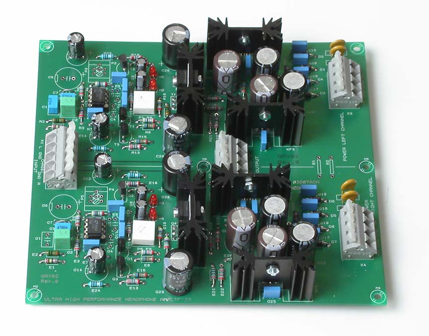
QRV-02 - The high performance headphone amplifier with multiple feedback
Click on the picture to get a larger view.
I designed this amplifier as a result of reading postings at HeadWize. The forum is I'm afraid closed down.
I call it "underkill amp" or "Cmoy deluxe". The performance is outrageous in headphone amp terms. See the technical data!
Interesting features:
- The pcb fits virtually any single opamp with or without offset trim.
- Room for good coupling caps (if you must or like)
- Input LP-filter if you have problems with RF interference (you should have a filter though).
- Room for DC removal cap (if you need this).
- Crossover distortion reducer for the opamp.
- Current limitation inside the feedback loop (choose the value you like)
- Local feedback for stable performance (only if necessary)
- High quality power supply with large smoothing caps. No transformers on the pcb.
- Fits any headphone (except for electrostatic of course).
My design goal was to make a simple but well balanced amp in terms of component choices and a well-tested topology. The amp needs only high quality industrial parts in order to work good. No special (or odd) audiophilic parts are needed but if they fits, no harm in using them as long as they have minimum performance in electrical terms.
The amp works in class A as much it's possible.
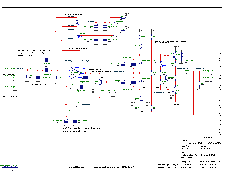
The schematics, page 1 and 3.
Click on the picture to get a larger view. The picture shows the schematics of the amp. Of course you can't use it for anything except for an overview. Please download the pdf-file instead if you want to see the details.
The main part
The main part is an operational amplifier, IC1. The opamp is followed by a buffer capable of up to 1 A which will be sufficient for all headphones on the market. In between the opamp and the buffer I have put a class A circuit, T1, R8, R9 and H3. This circuit was an experiment and is most effective when the load at the output of the opamp is small, not in this case. This circuit here is not very effective, don't use it, is my recommendation. You can take advantage of the circuit if you make the buffer different, maybe with MOSFET's.
Frequency compensation
R4, C5 is for frequency compensation. C4 is only for LT1028/LT1115!!
Offset trimming
P2, P3 are only used if you don't use a precision opamp. Weather P2 or P3 should be used, consult the datasheet of the opamp. Avoid these offset trimming pots. If you use them you will get worse temperature characteristics and worse power supply rejection. The later may not be so important.
The gain
The total gain is determined by R6 and R7. Gain = R6/R7 + 1. Low values of these resistors is important if you want low noise. Frequency compensation is achieved by R4 and C5.
Multiple feedback
R5 is an option for multiple feedback. Those who know what that is can expemeriment with R5, R4 and a jumper wire in C5. I havn't tested this and it's unsupported from my side.
Output current limitation
R19 isn't necessary but this resistor creates current limitation which means that both low impedance och high impedance headphones can be connected. Without this resistor it's very easy to damage low impedance headphones but if you have full control over the situation, omit this resistor. I should mention that many headphones are designed to be driven from a certain source impedance. Some people claim that this impedance is 120 ohms. Test this if you want to optimize the listening experience.
The input filter
The input filter is very universal. You should have a lowpass filter, R2 and C1, but if you don't have any RFI trouble at all, it's not necessary, just replace the R2 with a jumper and omit C2. DC blocking capacitor may be necessary but check with your signal source first. The whole amp is DC connected so you must ensure that you haven't got any DC in your signal.
Set class A level
If you don't want to trim the idle current you can omit P1, R15, R16 and T4. The LED's creates sufficient idle current of T5 and T6. If you want more current in an easy way, change colour of the LED's! If you have T4 mounted you can either have or loose the LED's. If you do have the LED's you will get a limitation of max bias current.
The output transistors
The output transistors must be insulated from the heatsink, see picture (not published yet, in the meantime, drop me a note.
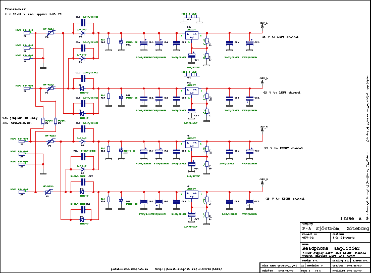
The schematics, page 2
Click on the picture to get a larger view. The picture shows the schematics of the amp. Of course you can't use it for anything except for an overview. Please download the pdf-file instead if you want to see the details.
The power supply
The power supply is not very exotic, rather straight forward. It's designed to use two transformers but it's possible to use one only, just use the jumpers B1 and B2.
The regulators have heatsinks but in light duty and/or with low supply voltage, they aren't really necessary. You must insulate the regulators from the heatsinks.
R23, R24 are bleeder resistors. The regulators won't discharge the capacitors completely when the have reached the voltage of 0,6 V. The resistor creates a clean start at power up.
DZ1 is for transient protection, not necessary if you don't have problems of this nature.
F1 is a PTC fuse, lasts "forever".
The pcb layout
The component print
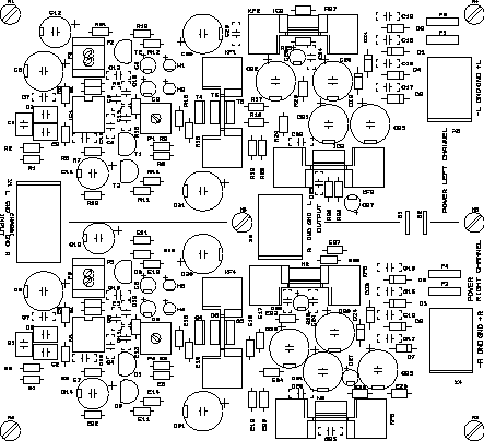
The picture shows the component print of the PCB. Of course you can't use it for anything except for an overview. Please download the pdf-file instead if you want to see the details.
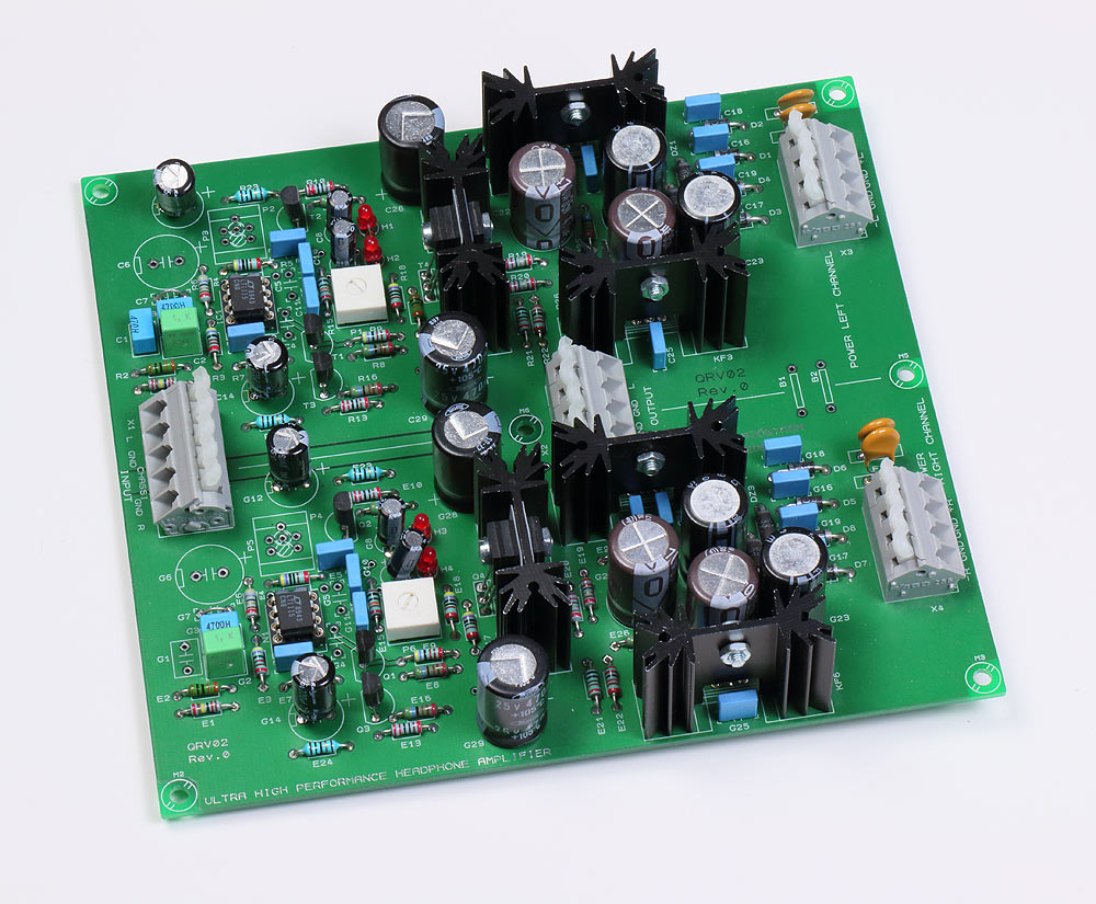
The printed circuit board is made for two channels, contains everything, power supply and the amp itself except for connectors and transformer (or transformers). I have chosen not to have pcb mounted headphone and phono connectors because it's hard to fit in a case. My goal here is the use a 1 HE high case. You will need one or two transformers.
The pcb have groundplane on the upper side (not shown in pictures) which is essential in order to get good results.
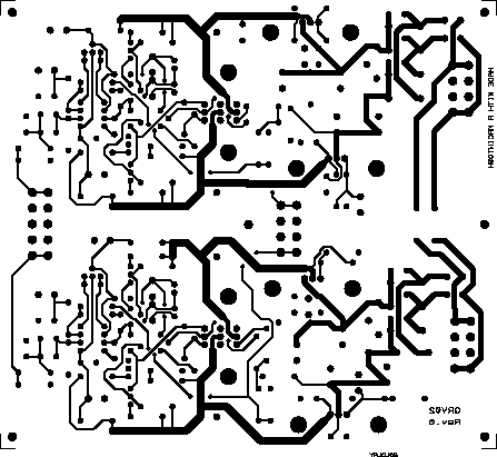
The solder side
The picture shows the solder side of the PCB. Of course you can't use it for anything except for an overview. Please download the pdf-file instead if you want to see the details.
Almost everyone of the traces are on the solder side. The groundplane is very covering, only a few traces on the component side, see below.
The component side
The picture shows the component side of the PCB. Of course you can't use it for anything except for an overview. Please download the pdf-file instead if you want to see the details.
Almost everyone of the traces are on the solder side as you can see. The groundplane is very covering, only a few traces on this side.
The groundplane mask
The picture shows the groundplane mask of the PCB. Of course you can't use it for anything except for an overview. Please download the pdf-file instead if you want to see the details.
The black area is without groundplane.
The hot relief pads
The picture shows the pads which are connected to groundplane of the PCB. Of course you can't use it for anything except for an overview. Please download the pdf-file instead if you want to see the details.
Each "cross" at the pads is a ground connection. This file is used together with the component side in a sandwich. I use this technique because my cad program has a very slow groundplane generation.
Build directions
This design is very easy to build. You can of course solder everything and then apply voltage but maybe it doesn't hurt to be a little cautious.
Start with the regulated power supply.
- Diodes
Resistors
Polyester caps - Connectors
- Then continue with the high electrolytic caps, mount all caps, also the ones located at the amp itself.
- And final with the heatsinks with mounted regulators. The regulators don't have to be isolated towards the heatsinks. You don't need heatsinks in light duty or if you have low supply voltage.
Apply voltage, 2 x 18-33V DC or 2 x 15-24 V AC and check that you'll get plus 15 volts and minus 15 volts. Measurement points are pin 7 and 4 at IC1, N1. Disconnect the power and see to that the voltage is zero when you continue the soldering. You can have lower voltage but then you'll have to recalulate the voltage regulators.
Continue with the amplifier itself.
- LED's
Resistors
Polyester caps
Small signal transistors, but skip the class A circuit. - IC socket if you want to test different opamps but I recommend that you avoid sockets (bad contact with time). If you do want sockets, use high quality with "tulip" contacts. See the picture.
- Then continue with the power transistors and the heatsink. Mount all three transistors first at the heatsink, then cut the legs so they become not equally long. It's much easier to fit nine pins in the holes that way.
Check the output stage
Apply voltage again and check the output stage. The LED's should be lit. Measure the voltage across R17, R18 but be careful so you don't slip. Expected voltage around 1 V. You could also apply a small signal.
Put in the operational amplifier
Now it's only one part left, the opamp. Solder it in (or put it in the socket).
The whole amp is ready.
Apply supply voltage. Measure the DC output voltage. Should be less than 5 mV.
Good luck and happy listening.
Listening experience
How does it sound really? Together with my Sennheiser HD545 Reference it sounds splendid to be short. Since I wrote this I have listened more. My impression is that the amp leave no traces behind, sort of speaking. I find that the colouration of the sound is minimal, none in fact.
I have tested with LT1115, OPA627 and OPA134. All of them are very good, can't hear any difference but I'm sure other people can. Drop me a note if you have any interesting information in this area.
Technical data
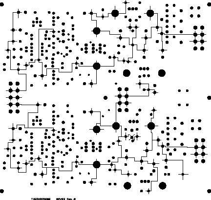
Click on the picture to see a preview of the pcb.
The pcb is tested with LT1115, LT1028, OPA627 and OPA134. Virtually any opamp fits if they have proper characteristics. If you are unsure, drop me a note and I can give my point of view.
| Frequency response: | 0 Hz - 2,5 MHz, -3 dB, LT1115 0 Hz - 1,0 MHz, -3 dB, OPA627 0 Hz - 1,0 MHz, -3 dB, OPA134 |
| Frequency response with input filter | 1,5 Hz - 338 kHz, -3 dB |
| Power bandwidth at 10 Vrms, 50 ohms: | 0 Hz - 190 kHz, -3 dB, LT1115 0 Hz - 700 kHz, -3 dB, OPA627 0 Hz - 250 kHz, -3 dB, OPA134 |
| Equivalent input noise: | 100 nV, LT1115 600 nV, OPA627 1,2 µV, OPA134 |
| Signal to noise ratio: | 137 dB, LT1115 122 dB, OPA627 116 dB, OPA134 |
| Dynamic headroom: | 157 dB, LT1115 142 dB, OPA627 136 dB, OPA134 |
| Distortion: | < 0,0002 %, LT1115 < 0,00003%, OPA627 < 0,00008%, OPA134 |
| Slew rate: | 15 V/µs, LT1115 55 V/µs, OPA627 20 V/µs, OPA134 |
| Step response: | Perfect with a minor overshoot, LT1115 Perfect without overshoot, OPA627 Perfect without overshoot, OPA134 |
| Gain: | 11 (21 dB) |
| Input impedance: | 47 kohms |
| Output impedance: | 3 milliohms |
| Damping factor: | 16000 with 50 ohms load |
| Output current: | 1 A peak |
| Supply voltage: | +- 18-33 V DC, 2 x 12-24 V AC |
| Current consumption: | 100-200 mA idle, max 1,4 A, with headphones connected not more than the idle current. |
| Dimensions: | 157,5 (6,2") x 142,2 (5,6") mm |

