Build directions
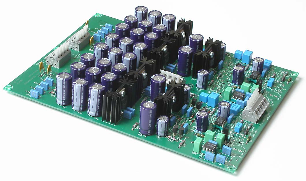
Click on the picture to get a larger view. The printed circuit board of the QSX Mark III Amplifier.
Before you build, take a look at possible component selections. You can choose from two different output stages, chopper stabilized DC-servo, regular DC-servo or trimpotentiometer.
Start with the power supply
Solder in all (check first which passive parts you need) low passive parts (also diodes) for the whole amp. Wait with transistors, regulators, IC's and heatsinks. Notice which parts which are associated the bipolar output stage and with the integrated buffer.
Mount the regulators on the heatsinks. Only the negative regulator, 7915 need to be isolated from the heatsink. You will need a bushing, see the picture below, in order to isolate the screw from the tab. I recommend silicone rubber. There is nothing wrong to use mica washer or Kapton film (orange, very thin). Mount the regulators first at the heatsink, then mount the heatsinks at the pcb.
When the regulators are in place, solder in all big electrolytic caps, even those located at the amp.
Apply voltage to one channel at the time. Check that the voltage is plus 15 volts and minus 15 volts. Suitable measurement points are IC1, pin 7 and 4. Do the same thing with the other channel. Disconnect the supply voltage and make sure that all of the caps are completely discharged. The check the voltage in the IC1, pin 4 and 7. It must be less than 0,6 volts! This is only a precaution.
The output stage
Decide which type of buffer you are going to use, bipolar discrete or integrated.
The bipolar (BJT) output stage
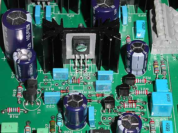
Click on the picture to get a larger view.
The following parts are associated with the bipolar buffer: R18-R24, R67-R73, T3-T8, T11-T16, D3-D6, D15-D18, C22, C23, C75 and C76. The transistors have to be isolated from the heatsink.
The transistors have isolated holes so you don't need bushings. I recommend silicone rubber. There is nothing wrong to use mica washer or Kapton film (orange, very thin).
The monolithic (LT1010) output stage
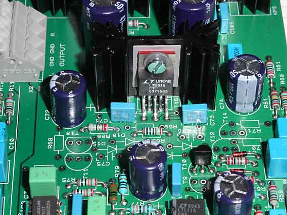
Click on the picture to get a larger view.
I recommend the buffer as output stage. It costs a little bit more but the performance is higher, distortion lower. The following parts are associated with the bipolar buffer: R16, R17, R65, R66, IC2, and IC7
The buffer needs to be isolated from the heatsink. You will need a bushing, see the picture, in order to isolate the screw from the tab. I recommend silicone rubber. There is nothing wrong to use mica washer or Kapton film (orange, very thin).
DC-servo
You can choose from four options:
- Chopper stabilized operational amplifier with external auto-zero caps, MAX420, R25-R29, R74-R78, C24-C30, C77-C83, IC3 and IC8.
- Chopper stabilized operational amplifier with internal auto-zero caps, MAX430, R25-R29, R74-R78, C24, C25, C28-C30, C77, C78, C81-C83, IC3 and IC8.
- Conventional precision operational amplifier, R25-R29, R74-R78, C24, C25, C28-C30, C77, C78, C81-C83, IC3 and IC8 (OP07 or similar), P3, P7 or P4, P8, depending on chosen opamp.
- Plain trim potentiometers, P1, P5 or P2, P6, depending on chosen opamp.
All opamp choices are good but they are listed in performance order. I don't recommend trim potentiometers but I have made room for them anyway.
The Class A circuit
You can choose from three options:
- JFET, current source, T1, T9, R14 and R63. The value of these resistors need probably adjustment, higher value, 500 ohms or higher.
- BJT, current source, T2, T10, R14, R15, R63, R64, D1, D2, D13, D14
- Plain resistor, R14, R63 connected directly to the output. Suitable value 6.8-10 kohms.
The class A circuit can be omitted but it makes most benefit when the load from the opamp is small like when you use the LT1010 buffer.
The RIAA network
I have made the pcb so you can use the original Linear Technology design or my own.
You can choose from two options:
- The original Linear Tech design, without DC-servo. Compare with the datasheet and the schematics and check for which parts you have to use and also the parts which need changed values.
- My version, De Luxe! C6-C10, C31, C59-C63, C84, R4, R6, R8-R12, R32, R33, R53, R55, R57-R61, R81 and R82.
Omit R5, R7, R13, R54, R56, R62, C3-C5, C11-C13, C56-C58, C64-C66
Input filter
If you don't have any RFI problems, replace the R2, R51 with a jumper. R1, C1 and R50, C54 maybe need to be adjusted. Consult the datasheet of your MM pickup. If you are planing to use MC pickup, the load is R3, C2 and R52, C53. The capacitor for the MC load is not very critical, so I've heard.
The operational amplifier, the final part
Solder in only IC1 and IC6. Use IC sockets for test purposes only. If you use sockets permanently, use high quality ones with "tulip" contacts. I recommend not to use IC sockets. Short the input to ground or place a jumper at J1 and J3.
Check one channel
Apply supply voltage just this channel. Measure the output DC voltage. Should be ZERO with a MAX420 opamp and less than 2 mV with a regular opamp. Just to be sure, check the supply currents. Use R41 and R49 as current shunts. The current value should be ????
Check the other channel
Apply supply voltage for both channels. Measure the output DC voltage. Should be ZERO(!) with a MAX420 opamp and less than 2 mV with a regular opamp. Just to be sure, check the supply currents. Use R90 and R98 as current shunts. The current value should be ???? Connect a pick to the input. The amp should work now!
The whole pcb
Click on the picture to get a larger view.
The complete phono amp with all components soldered in. The left channel has a bipolar output stage and the right channel has an integrated buffer as output stage. This is only for the picture taking. I have also listened to the amp different output stages, can't hear the difference. I guess that LT1010 is slightly better than the bipolar stage.
