QRP-02 - The first SMD Gainclone amplifier in the world(?)
Click on the picture to get a larger view.
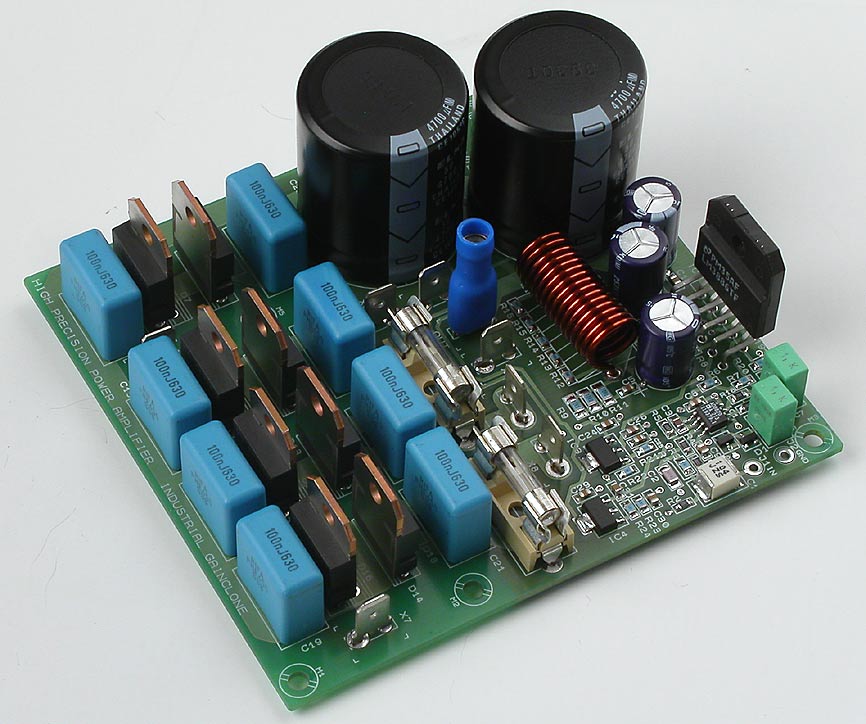
The world's first DIY SMD Gainclone
Specifications for the new advanced Gainclone.
- 50 um pcb with groundplane
- Fast recovery rectifier diodes, TO247 and option for TO220
- High performance 4700 uF/50V max, 10 mm snap-in and regular ones too.
- LM3886, inverting, 1k+18k, properly decoupled
- Mute
- Output filter, 14 turns, diam 8 mm, 1.5 mm wire, 5 mohms, 0.7 uH (I can get those inductors free of charge)
- Zobel network
- DC-servo, AD8620, properly decoupled (possible not to use it)
- Input buffer, non-inverting, 220 kohms input impedance, AD8620, properly decoupled.
- LM317/337 in SOT223
- All elctrolytic caps hole mounted
- SMD caps PPS, X7R, NPO types, 0805, 1206, 2220 size
- SMD resistors, 0805
- Lug connectors with option for 2.5 mm2 wires
- Fuses 5 x 20 mm
A complete product, a mono block
Click on the picture to get a larger view.
The goal is a complete product, just add two windings with AC, signal in and speaker out and a cute small pcb.
Please download the AN-1192 and try to understand this very good application note. Much of this design is based on this application note. I have made some adjustments but the basic idea is very good.
Overture_Design_Guide13.xls (and instructions for the file) is a very good tool when you want to estimate needed transformer and other power supply parts, heatsink etc. If you can't get these files, send me a message and I'll send those to you.
The design consists of an input buffer, the power IC, LM3886, an extremely high performing DC-servo, a power supply and a rectifier bridge. The thing which is missing is only a transformer.
Lower distortion
Inverting configuration is chosen for the LM3886 and the reason for this is ten (at least 2-5) times lower distortion. Those people which have problems with that may switch the speaker cables.
Pop and click free
Since the basic design already is tested in my other Gainclone project I'm quite confident that this very cute little pcb will perform to full satisfaction. The first listening impressions points in that direction. One problem that many Gainclone builders experience is DC shifts, pops, hump, click etc at power down and power on. This design is totally pop free! The secret is that the buffer works low below +- 12 volts where the undervoltage protection works for the LM3886. LM3886 has also an effective mute function which ensures a smooth startup.
Low impedance drive
The LM3886 is driven from a low impedance buffer which makes it possible to use rather low resistor values for the feedback. This is good because all stray capacitances will have less influence. The feedback network gets more ideal, more resistive, higher up in frequency. The usage of SMD resistors makes this even better. This is a positive thing for stability, clean behavoir and performance in general.
The input buffer
AD8620, is chosen as a buffer because it's a really, really good opamp. The most impressing feature besides the sound quality is the extremely low offset voltage, around 70 µV! The same opamp works also as DC servo which makes it in world's class, an extremely high performing DC servo. This DC servo is the best world has seen so far. Am I wrong?
The buffer accomplish also an effective buffering and isolation from the signal source. This means low interaction between power amp and signal source. Since a non-inverting buffer is used the input filter can be taylored to suit your demands in any way you like. The gain is minimal (slightly over 1) but can be tuned to any value above 1.
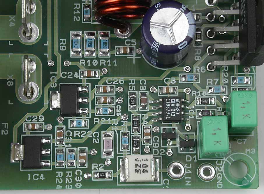
Click on the picture to get a larger view. Detail of the input buffer
Power supply
As you may have noticed I have not chosen to have each rail voltage on each side which is common pratice. I have chosen to have all the power at the left side of the pcb and have sensitive signals on the right side. The pcb gets a bit "unbalanced" to the looks but electrically it feels better. As you also can see I have made an option for "plain" electrolytic caps and for heavy duty types with snap-in pins. I have also high performance decoupling accomplished by SMD caps of 100 nF very close to the power supply pins of the LM3886 and the caps go directly down to groundplane. Half the success is proper supply voltage which is not very easy to get unless you have a good pcb with groundplanes.
Rectifier bridges
I really recommend you to have two separate windings connected to two separate rectifier bridges. You can either have really big TO247 diodes which costs a lot and may be overkill technically but you can also have TO220 types which are much cheaper and more "normal" and definitely sufficient. Both diode types can be attached to a heatsink. The gap between the diode rows is for this purpose but please beware of that the diodes needs insulation.
You can also use only one rectifier bridge. See a special intruction for this. Then you will not use X3 and X7 but X5 and X6 will be used instead.
Transformer
The design is a mono block, meaning you must have one transformer to each pcb. Suitable size is 80 VA as minimum, 100-160 VA as normal and 225-300 VA is "serious". 400 VA and above is overkill. Recommended voltage is 2 x 22-28 VAC. 2 x 30 VAC gives you a voltage just at the edge of what the LM3886 can take. I don't recommend it.
The schematics, page 1
Click on the picture to get a larger view. The picture shows the schematics of the amp. Of course you can't use it for anything except for an overview. Please download the pdf-file instead if you want to see the details.
This page shows the power supply except for the transformer.
Transformer
The design is a mono block, meaning you must have one transformer to each pcb. Suitable size is 80 VA as minimum, 100-160 VA as normal and 225-300 VA is "serious". 400 VA and above is overkill. Recommended voltage is 2 x 22-28 VAC. 2 x 30 VAC gives you a voltage just at the edge of what the LM3886 can take. I don't recommend it.
Rectifier bridge
The power supply consists of two rectifier bridges where you have either TO247/218 diodes (double with common cathode) or smaller TO220 diodes. I have chosen 8-10 A fast recovery diodes of type MUR820/860 (double with common cathode) which comes in TO220 and 30 A MUR3020PT which comes in TO247/218.
Both types are placed "back to back". They are on a line so if you want the have some extra cooling you can mount all diodes on a metal bar, but I don't think it's necessary for normal home use. The diodes type I have chosen is fast recovery but it's not verified how much they will improve performance compared to soft recovery, normal recovery or even schottky diodes. Which diode type you will choose is only a matter of taste and choice. The smaller type is quite enough. Two rectifier bridges assume that you have two separate secondary transformer windings but if you have a centertapped transformer you may be able to use one bridge.
RFI filter
Each diode is decoupled with a high performance and heavy duty polypropulene capacitor from RIFA EVOX, PHE450. It's recommend but other types with different pin spacing will fit.
C14-C21 will reduce harmonics which is caused by when the diodes are switching currents. 100 nF is "something". it is not investigated if it's enough or not. It's probably OK or somewhat high. Sometimes you also have a resistor is in series with the cap, like 1-10 ohms and sometimes up 100 ohms.
Center tapped transformer
D3, C14, D5, C16, D12, C19, D14, C21 (or D7, D9, D16, D18), F1, F2
AC in at X4 and X8
Center tap at X5, X6
Wire jumper D13, pin 1 to D4, pin 3 and D11, pin 1 to D6, pin 2
Smoothing
There are two alternatives as smoothing caps, expensive ELNA LP3J high performance caps in 10 mm snap-in and regular 5 or 7.5 mm caps which can be any suitable high performance type. I have chosen Jamicon WGR but this is only an example.
C23, C28 are the smoothing and those caps are high perfomrnance caps with 10 mm snap-in mounting. 4700 uF is choosen but more or less can be chosen but I don't recommend less than 2200 uF. I have seen on the net down to 1000 uF. For maximum flexibility there are also room for plain caps with both 5 (2") and 7.5 mm (0.3") grid.
Regulators
The regulators are two LM317/337 regulators. I have chosen those because the can take 47 volts in max (at 12 volt out) and the are pretty cheap and also the AD8620 isn't so demanding. Plain 7812/7912 regulators can only take 35 volts in.
The regulators, IC3 and IC4 are for the opamps and the design is pretty common and simple. The voltage is set to +12 V and -12 V. AD8620 can take max +- 13.6 V. C25 and C30 are for improving transient characteristics. R22 and R24 are increased from recommend 220 ohms to 1 kohms only for not adding just another resistor value and also improve the effect of the rather small C25, C30. I didn't want to have an another capacitor type, that's why is chose this value. Optimal value is around 10-22 uF.
You may experience oscillations at 100 kHz or something and the reason for this is that the total capacitance may land in the forbidden area of the regulator. LM337 is the most sensitive for this. If you are having problems with oscillations, just remove C31. You could also add 10-22 uF.
The schematics, page 2
Click on the picture to get a larger view. The picture shows the schematics of the amp. Of course you can't use it for anything except for an overview. Please download the pdf-file instead if you want to see the details.
This is the amp. A dual operational amplifier serves as an input buffer and a DC servo.
R1 is only a pulldown resistor and can be of any value, even up to 1 Mohms or more. The purpose of the resistor is to not let the C1 capacitor get charged which may happen when the input is unconnected. If you connect the amp to a signal source when the amp is powered on you can get a nasty transient but mainly you will avoid a click in the speakers. I have chosen 220 kohms only because I use this value in the R2 position.
C1 is optional and may be used if you aren't 100% sure that your signal source hasn't got any DC out. I have chose to use a polyphenylene sulphide capacitors just because I thought polyester wasn't cool enough. At the moment there are no audiophilic caps which are surface mounted and I know only two good types, polyphenylene sulphide and polyester. According to my experience physically small polyester caps are better than it's rumour.
C1 together with R2 forms a highpass filter and the cutoff frequency is 7.2 Hz. R2 determines also the input impedance in parallel with R1. If you of some reason aren't satisfied with 7.2 Hz and you think this cut frequency is a bit high, you could change this very easily, place an another capacitor on top of the C1 (it's real easy to solder since this are SMD caps) or increase the R2.
R3 and C2 forms a lowpass filter and is wise to have. The filter cut off frequencies above 72.3 kHz. The value I have chosen seem to be fair. It should less than the slew rate limiting of the LM3886 which is 90 kHz.
The quality of C2 should be good and a NP0 type is a good choice.
The buffer, IC1 is often necessary in order to get a good match between the impedance of signal source and the input on the LM3886 amp. I have chosen one of the best opamps in the market at the moment, an AD8620 from Analog Devices. This opamp has extremely high performance when it comes to audio quality. A good choice is also OPA2134 and many, many more types. If you have an another suggestion and aren't sure, just ask me and get my point of view.
The gain of the buffer is almost 1. R4 serves more like place holder but I have chosen to have some value at this position. 8.2 kohms in the regulators, so that's the value I have chosen. It can be anything between 5.6 kohms to 47 kohms or even more. The reason why the opamp can have gain is only for flexibility. Somebody may want more gain or less for the LM3886. C3 is only a "value" serves rather little purpose. If the gain is 10 or more it's important to have a capacitors in this position in order to cancel out the input capacitance of the opamp. If this input capacitance is not take care of, oscillations may occur. If the gain is close to one this capacitor isn't very important, especially if you have low resistor values as feedback.
One half of this dual opamp is used for the buffer and the other is used for a DC servo. The servo can be disconnected if the DC offsets are less than 50 mV. With this servo you get an output offset voltage of 70-80 uV! Since the opamp itself is extremely good the influence of the servo be almost zero. One conditions for this is that the servo is designed with care. I have used LTSpice to "tweak" in all component values. It's very important that every part are carefully selected. If you want to play with the simulation files, just send me a message.
The servo consists of a plain integrator, R17 and C6 with D1 and D2 as protection (hardly necessary). At the integrator output we have an attenuator, R18-R20 which determines the offset adjust range of the servo. The range is about 1/100 of the max output from the servo, +- 100 mV. C7 blocks any audio signal coming into the servo and it blocks also audio signal from the main input being fed back into the LM3886. This C7 creates a little hump in the lowest bass but we talk about 0.05 dB so I think we can live with it. Perfectly flat frequency response is achieved if you omit the C7.
The LM3886 is the heart of the design. Please download the datasheet for fully understand the IC and it's benefits. Overture_Design_Guide13.xls (and instructions for the file) is a very good tool when you want to estimate needed transformer and other power supply parts, heatsink etc.
Most amps have has 10 times lower distortion if it's used in inverting mode compared to non-inverting mode. This the reason why I have chosen inverting mode but I haven't been able to confirm if the distortion really is lower in inverting mode.
I have chosen to have rather ohmish feedback (possible with a buffer) because you will get a more "pure" feedback and all stray capacitance's will have less influence. The LM3886 will work under more ideal conditions and the feedback will remain resistive higher up in frequency. This is good for stability reasons.
R8 and C4 is the mute circuit. This will make the amp startup smoothly and together with the internal undervoltage protection shut down without any pops or clicks. This is also confirmed that this is the case.
R8 is chosen to be as large as possible in order to get a long delay as possible with 100 uF. R8 must not be too large, too large and you will have a permanent attentuation. See the datasheet about this.
C10-C13 is decoupling for the LM3886 and is important in order to get an problemfree operation. Many DIY'ers don't pay attention to this!
R9-R11 and C5 is a Zobel network and is usually important. This network is frequency compensation for the output stage of the LM3886. This filter moves a pole higher up and by that avoids oscillations. The absence of this filter may more often than the average DIY'er think cause a degradation of the sound quality. Some people think that less parts are better but they don't know really what each part does. Therefore they remove too many parts and also important ones!
R9-R11 are chosen so they can handle 20 kHz at full output power. If you want to test full power bandwidth, remove these resistors or change them to something bigger, otherwise you will have a characteristic smell.
L1 and R12-R16 is also an important filter.... which is omitted by many DIY'es. This filter isolates the amp from capacitive load. Long speaker cables have capacitance and some exclusive cables have even more. This can cause unstability and give a degradation of the sound quality. Expensive cables may sound worse than cheap ones! This filter avoids this and let expensive cables give the owner value for his money. In order to increase the "fidelity" of the inductor I have used extra thick wire, 1.5 mm in diameter. If anyone wants help with winding this inductor, just mention this when you order the pcb. It's easy to wind this inductor nicely but it requires some technique and tools.
Gain
The gain for the input buffer is R5/R4 +1 and for the LM3886 R7/R6. The LM3886 has the gain of 18 (25dB) and you should not change this becaue this will have influence on the DC servo. If you of some reason must change the gain, you must also recalculate the servo. My advise is to only change the gain of the input buffer wich is now only 1.3 (2.1 dB) and can be changed from 1 to at least 100.
Total gain is (R5/R4+1)*(R7/R6) = 22.8 (27 dB)
The pcb layout
Click on the picture to get a larger view.
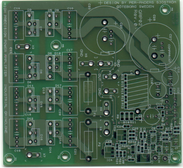
The component print
The picture shows the component print of the PCB. Of course you can't use it for anything except for an overview. Please download the pdf-file instead if you want to see the details.
The printed circuit board is made for one channel, contains everything, power supply and the amp itself except for connectors and transformer (or transformers). You will need one or two transformers. Two transformers if each one only has one secondary winding.
The pcb have groundplane on the lower side (not shown in pictures) which is essential in order to get good results.
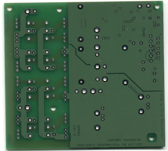
The solder side
The picture shows the solder side of the PCB. Of course you can't use it for anything except for an overview. Please download the pdf-file instead if you want to see the details.
Almost everyone of the traces are on the component side. The groundplane is very covering, only a few traces on the solder side, see below.
The component side

The picture shows the component side of the PCB. Of course you can't use it for anything except for an overview. Please download the pdf-file instead if you want to see the details.
Almost everyone of the traces are on the componen side as you can see. The groundplane is very covering, only a few traces on the solder side. As you can see from the picture above, all power traces are on the left side and all signal circuits are on the right side. Common pratice so far is to mix power and signal just to get a symmetrical pcb but I have put signal quality in the first room and symmetry and pcb looks in the other.
The groundplane mask
The picture shows the ground plane mask. Of course you can't use it for anything except for an overview. Please download the pdf-file instead if you want to see the details.
The groundplane consist of two halfs, one for the power currents and one for signal ground, at the right. The rectifier bridges have no groundplane because there is no need for it.
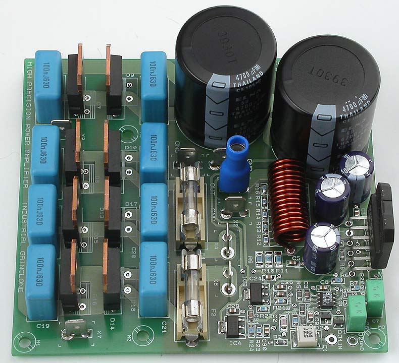
The real pcb's
Click on the picture to get a larger view.
This is the real pcb's.
Listening experience
Click on the picture to get a larger view.
I, Per-Anders Sjöström says:
With MUR3020 diodes, 2 x 4700 uF heavy duty caps ELNA LPJ3, 200 VA, 2 x 24 VAC, buffer AD8620, otherwise according to the original design, this amp really sings.
Reptile fast deep bass, snappy, firm, dry, warmth in the mids, razor-sharp treble, very good "S"-sounds, simply a crystal clear sound. I'm quite surprised that the LM3886 is as good as it really is.
I think everyone should be aware of that this LM3886 isn't the solution for every audio problem but it's an excellent start for the Do-It-Yourself hobby. Some loudspeakers will probably don't like the LM3886 but pretty many will.
Walter from Belgium says this:
As stated in my previous posts, my findings regarding the sound of the amp are exactly the same as Andy's. The thing works is magic from the first second. While other amps need a break-in period, this one produces a clear and detailed sound right after you finished assembling. Bass is well proportioned, yet not dominant. The high's are crispy but not that annoying SSSS timbre. The mid's are in my case a bit pronounced but this is speaker related. As soon as my other hobbyroom / bedroom speakers are finished I will have a better picture. The overall sound is very coherent and quite pleasing.
I also noticed that some sounds, like little bells and echoes, are not coming from the speakers. These are things that I didn't heard before, which is weird because some of the CD's that I've tested with I played many times before. I can't say if it runs cooler or hotter than my other amps. This is related on how loud you play and for how long. Absolutely no clicks or plops or whatever when powering up or off. Only things needed are some in-and output connectors and a transformer, and if you really need it a power on/off switch.
My monoblocks are equipped with 225 VA tranny's and 2A fuses. After cranking it up quite hard, just wanted to know how hard it could play, the fuses didn't blew. Regarding the SMD stuff I can see no reason why this should scare anyone of. I had absolutely no problems with soldering those little suckers. If one works carefully and don't rush things this is not more difficult than through hole. To conclude: a very nice and pleasant sounding amp, compact design and very complete. To P-A my compliments on a job "well done".
One week later....
In general my comments of previous posts still stands. What I do experience now after listening for a certain period of time that some of the harshness, if I even can call it that, is gone. Is it because the components are settling in or am I getting used to the sound I don't know. The music it reproduces is very smooth, detailed and open. What I like the most is the spatial image the amplifier creates. I'm also still amazed by the fact that a $5 chip accompanied by some SMD's can produce such a mature sound. All I can say is that this little amplifier produces a BIG sound.
Anders from Norway says this:
My observations so far:
- Very silent switch on and off.
- The sound was very good right from the start (no burn-in needed).
- It's very quiet regarding to hiss and 50 Hz even if my temporarily wiring are very spaghetti-like.
- It's slightly warmer (temperature) than my LM3875.
- I like the sound - very open and detailed without getting harsh.
- It's nice to have everything on one board (only add transformer).
- Fairly easy to build if you have two soldering irons and a good magnifying glass - even with my shaking hands.
This is a successful project!
One week later....
Same with me (as with Walter). I have been playing a lot of CD's and are often amazed with the clarity and perspective of the sound.
The result have been better than my expectations.
My goal is to build active 3-ways speakers with 4 amps pr. speaker (two for the bass)
Why is it so good?
At the moment only three QRP-02 are built but all three produces as good quality as the LM3886 can. Some people claim that this isn't high-end and wrinkle their noses. OK, but it is very close and high-class "mid-end" is very good in this case. My idea why this is so good is the usage of an extremely good input buffer, together with an inverting mode LM3886 and also usage of low resistors values in the feedback. One other thing is the output filter which importance not shall be underestimated. Since the zobel network is made of SMD parts the high frequency characteristics are very good and works very good and does a very good job as frequency compensation for the output stage of the LM3886.
Technical data
Click on the picture to get a larger view.
For complete data, please read the datasheet for the IC's in mind.
| Output power: | 68 W at 4 ohms, see this for more info |
| Frequency response: | 0 Hz - 400 kHz, -3 dB |
| Frequency response with DC-servo: | 0,1 Hz - 400 Hz, -3 dB, without C1 7,2 Hz - 400 Hz, -3 dB |
| Power bandwidth at 20 Vrms, 8 ohms: | 0,1 Hz - 100 kHz, -3 dB, without C1 |
| Output offset voltage: | Less than 80 uV, typically 10-30 uV |
| Equivalent input noise: | 2 µV typical |
| Signal to noise ratio: | 92.5 dB at 1 W out |
| Signal to noise ratio: | 117 dB at 1 V in |
| Dynamic headroom: | 119 dB |
| Distortion: | 0,002 % |
| Slew rate: | 19 V/us |
| Step response: | Excellent, perfect. |
| Gain: | 19 (25.6 dB), inverting mode |
| Input impedance: | 100 kohms, with non-inverting input buffer |
| Output current: | 11.5 A |
| Gain bandwidth product: | 8 MHz |
| Dimensions: | 101 x 109 mm, 4" x 4.3" |
