The schematics, page 1
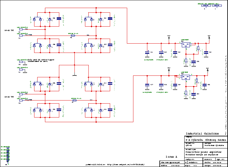
Click on the picture to get a larger view. The picture shows the schematics of the amp. Of course you can't use it for anything except for an overview. Please download the pdf-file instead if you want to see the details.
This page shows the power supply except for the transformer.
Transformer
The design is a mono block, meaning you must have one transformer to each pcb. Suitable size is 80 VA as minimum, 100-160 VA as normal and 225-300 VA is "serious". 400 VA and above is overkill. Recommended voltage is 2 x 22-28 VAC. 2 x 30 VAC gives you a voltage just at the edge of what the LM3886 can take. I don't recommend it.
Rectifier bridge
The power supply consists of two rectifier bridges where you have either TO247/218 diodes (double with common cathode) or smaller TO220 diodes. I have chosen 8-10 A fast recovery diodes of type MUR820/860 (double with common cathode) which comes in TO220 and 30 A MUR3020PT which comes in TO247/218.
Both types are placed "back to back". They are on a line so if you want the have some extra cooling you can mount all diodes on a metal bar, but I don't think it's necessary for normal home use. The diodes type I have chosen is fast recovery but it's not verified how much they will improve performance compared to soft recovery, normal recovery or even schottky diodes. Which diode type you will choose is only a matter of taste and choice. The smaller type is quite enough. Two rectifier bridges assume that you have two separate secondary transformer windings but if you have a centertapped transformer you may be able to use one bridge.
RFI filter
Each diode is decoupled with a high performance and heavy duty polypropulene capacitor from RIFA EVOX, PHE450. It's recommend but other types with different pin spacing will fit.
C14-C21 will reduce harmonics which is caused by when the diodes are switching currents. 100 nF is "something". it is not investigated if it's enough or not. It's probably OK or somewhat high. Sometimes you also have a resistor is in series with the cap, like 1-10 ohms and sometimes up 100 ohms.
Center tapped transformer
D3, C14, D5, C16, D12, C19, D14, C21 (or D7, D9, D16, D18), F1, F2
AC in at X4 and X8
Center tap at X5, X6
Wire jumper D13, pin 1 to D4, pin 3 and D11, pin 1 to D6, pin 2
Smoothing
There are two alternatives as smoothing caps, expensive ELNA LP3J high performance caps in 10 mm snap-in and regular 5 or 7.5 mm caps which can be any suitable high performance type. I have chosen Jamicon WGR but this is only an example.
C23, C28 are the smoothing and those caps are high perfomrnance caps with 10 mm snap-in mounting. 4700 uF is choosen but more or less can be chosen but I don't recommend less than 2200 uF. I have seen on the net down to 1000 uF. For maximum flexibility there are also room for plain caps with both 5 (2") and 7.5 mm (0.3") grid.
Regulators
The regulators are two LM317/337 regulators. I have chosen those because the can take 47 volts in max (at 12 volt out) and the are pretty cheap and also the AD8620 isn't so demanding. Plain 7812/7912 regulators can only take 35 volts in.
The regulators, IC3 and IC4 are for the opamps and the design is pretty common and simple. The voltage is set to +12 V and -12 V. AD8620 can take max +- 13.6 V. C25 and C30 are for improving transient characteristics. R22 and R24 are increased from recommend 220 ohms to 1 kohms only for not adding just another resistor value and also improve the effect of the rather small C25, C30. I didn't want to have an another capacitor type, that's why is chose this value. Optimal value is around 10-22 uF.
You may experience oscillations at 100 kHz or something and the reason for this is that the total capacitance may land in the forbidden area of the regulator. LM337 is the most sensitive for this. If you are having problems with oscillations, just remove C31. You could also add 10-22 uF.
The schematics, page 2
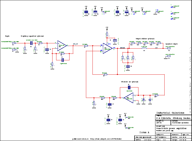
Click on the picture to get a larger view. The picture shows the schematics of the amp. Of course you can't use it for anything except for an overview. Please download the pdf-file instead if you want to see the details.
This is the amp. A dual operational amplifier serves as an input buffer and a DC servo.
R1 is only a pulldown resistor and can be of any value, even up to 1 Mohms or more. The purpose of the resistor is to not let the C1 capacitor get charged which may happen when the input is unconnected. If you connect the amp to a signal source when the amp is powered on you can get a nasty transient but mainly you will avoid a click in the speakers. I have chosen 220 kohms only because I use this value in the R2 position.
C1 is optional and may be used if you aren't 100% sure that your signal source hasn't got any DC out. I have chose to use a polyphenylene sulphide capacitors just because I thought polyester wasn't cool enough. At the moment there are no audiophilic caps which are surface mounted and I know only two good types, polyphenylene sulphide and polyester. According to my experience physically small polyester caps are better than it's rumour.
C1 together with R2 forms a highpass filter and the cutoff frequency is 7.2 Hz. R2 determines also the input impedance in parallel with R1. If you of some reason aren't satisfied with 7.2 Hz and you think this cut frequency is a bit high, you could change this very easily, place an another capacitor on top of the C1 (it's real easy to solder since this are SMD caps) or increase the R2.
R3 and C2 forms a lowpass filter and is wise to have. The filter cut off frequencies above 72.3 kHz. The value I have chosen seem to be fair. It should less than the slew rate limiting of the LM3886 which is 90 kHz.
The quality of C2 should be good and a NP0 type is a good choice.
The buffer, IC1 is often necessary in order to get a good match between the impedance of signal source and the input on the LM3886 amp. I have chosen one of the best opamps in the market at the moment, an AD8620 from Analog Devices. This opamp has extremely high performance when it comes to audio quality. A good choice is also OPA2134 and many, many more types. If you have an another suggestion and aren't sure, just ask me and get my point of view.
The gain of the buffer is almost 1. R4 serves more like place holder but I have chosen to have some value at this position. 8.2 kohms in the regulators, so that's the value I have chosen. It can be anything between 5.6 kohms to 47 kohms or even more. The reason why the opamp can have gain is only for flexibility. Somebody may want more gain or less for the LM3886. C3 is only a "value" serves rather little purpose. If the gain is 10 or more it's important to have a capacitors in this position in order to cancel out the input capacitance of the opamp. If this input capacitance is not take care of, oscillations may occur. If the gain is close to one this capacitor isn't very important, especially if you have low resistor values as feedback.
One half of this dual opamp is used for the buffer and the other is used for a DC servo. The servo can be disconnected if the DC offsets are less than 50 mV. With this servo you get an output offset voltage of 70-80 uV! Since the opamp itself is extremely good the influence of the servo be almost zero. One conditions for this is that the servo is designed with care. I have used LTSpice to "tweak" in all component values. It's very important that every part are carefully selected. If you want to play with the simulation files, just send me a message.
The servo consists of a plain integrator, R17 and C6 with D1 and D2 as protection (hardly necessary). At the integrator output we have an attenuator, R18-R20 which determines the offset adjust range of the servo. The range is about 1/100 of the max output from the servo, +- 100 mV. C7 blocks any audio signal coming into the servo and it blocks also audio signal from the main input being fed back into the LM3886. This C7 creates a little hump in the lowest bass but we talk about 0.05 dB so I think we can live with it. Perfectly flat frequency response is achieved if you omit the C7.
The LM3886 is the heart of the design. Please download the datasheet for fully understand the IC and it's benefits. Overture_Design_Guide13.xls (and instructions for the file) is a very good tool when you want to estimate needed transformer and other power supply parts, heatsink etc.
Most amps have has 10 times lower distortion if it's used in inverting mode compared to non-inverting mode. This the reason why I have chosen inverting mode but I haven't been able to confirm if the distortion really is lower in inverting mode.
I have chosen to have rather ohmish feedback (possible with a buffer) because you will get a more "pure" feedback and all stray capacitance's will have less influence. The LM3886 will work under more ideal conditions and the feedback will remain resistive higher up in frequency. This is good for stability reasons.
R8 and C4 is the mute circuit. This will make the amp startup smoothly and together with the internal undervoltage protection shut down without any pops or clicks. This is also confirmed that this is the case.
R8 is chosen to be as large as possible in order to get a long delay as possible with 100 uF. R8 must not be too large, too large and you will have a permanent attentuation. See the datasheet about this.
C10-C13 is decoupling for the LM3886 and is important in order to get an problemfree operation. Many DIY'ers don't pay attention to this!
R9-R11 and C5 is a Zobel network and is usually important. This network is frequency compensation for the output stage of the LM3886. This filter moves a pole higher up and by that avoids oscillations. The absence of this filter may more often than the average DIY'er think cause a degradation of the sound quality. Some people think that less parts are better but they don't know really what each part does. Therefore they remove too many parts and also important ones!
R9-R11 are chosen so they can handle 20 kHz at full output power. If you want to test full power bandwidth, remove these resistors or change them to something bigger, otherwise you will have a characteristic smell.
L1 and R12-R16 is also an important filter.... which is omitted by many DIY'es. This filter isolates the amp from capacitive load. Long speaker cables have capacitance and some exclusive cables have even more. This can cause unstability and give a degradation of the sound quality. Expensive cables may sound worse than cheap ones! This filter avoids this and let expensive cables give the owner value for his money. In order to increase the "fidelity" of the inductor I have used extra thick wire, 1.5 mm in diameter. If anyone wants help with winding this inductor, just mention this when you order the pcb. It's easy to wind this inductor nicely but it requires some technique and tools.
Gain
The gain for the input buffer is R5/R4 +1 and for the LM3886 R7/R6. The LM3886 has the gain of 18 (25dB) and you should not change this becaue this will have influence on the DC servo. If you of some reason must change the gain, you must also recalculate the servo. My advise is to only change the gain of the input buffer wich is now only 1.3 (2.1 dB) and can be changed from 1 to at least 100.
Total gain is (R5/R4+1)*(R7/R6) = 22.8 (27 dB)
