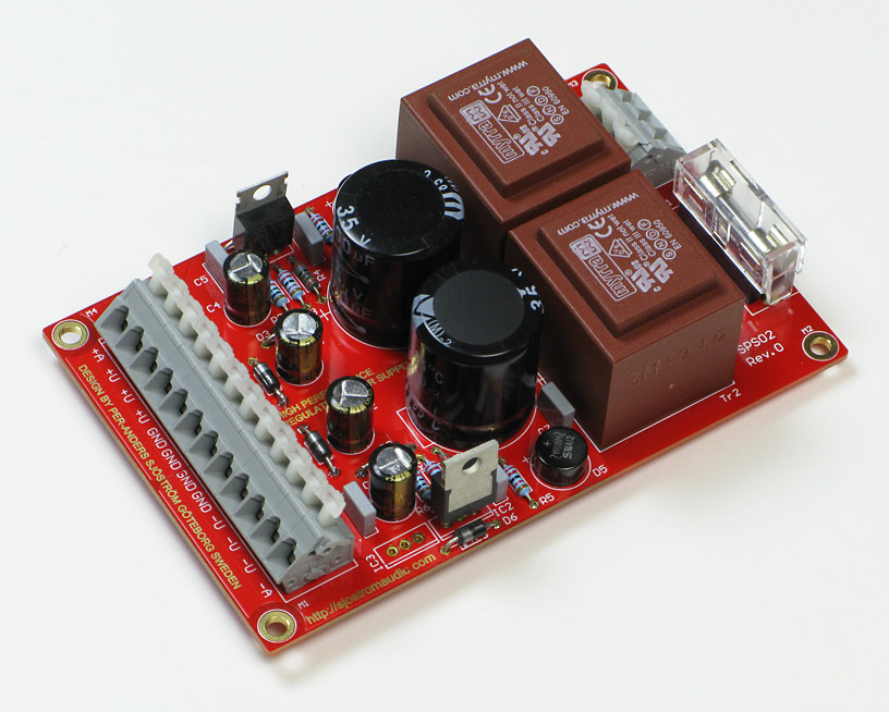
SPS-02 The Sjöström Power Supply
Click on the picture to get a larger view.
This design is a LM317/LM337 based regulated power supply, i.e. ±12 V or ±15 V (or any other voltage). It is made for general purpose usage, such as preamps, phono amps, tone controls and other electronic applications.
Interesting features
- 2-layer pcb.
- Gold pads.
- High quality pcb.
- Option for having two isolated output voltages.
- Option for having two positive output voltages.
The background
Click on the picture to get a larger view.
I have designed a LM317/337 based regulated power supply. Many people have asked me about this, so OK I'll do it. The difference between other designs of mine and this, is that it can be regarded as "normal" and rather simple in the meaning not complex. Most of my other designs are "ultra high performance" or even "extremely high performance" but this design is very good also since I have put much work into the pcb layout.
The design
Click on the picture to get a larger view.
A nice feature is that the design consists of two isolated regulators where the negative one can be equipted with an LM317 and creating a power supply with two positive voltages. It's no problem to make a 12 volt and 5 volt output or any other value from 1.2 volts and up.
The schematics
Click on the picture to get a larger view.
I recommend that you download the schematics and print it so you can follow the describing text more carefully.
Circuit description
The design consists of two independent sections, one positive regular with a LM317 as the main part. The other half is a negative regulator with a LM337. The design is taken more or less directly from the datasheet of the LM317 and the LM337
The positive half
The transformer is fused with 63 or 100 mA fast, 5 x 20 mm, European type. R9 is a varistor for transient protection. For 115 VAC this part must have a suitable value, from 150 VAC. The size should be K20.
The transformer type is 1.5-2.3 VA and the output voltage should the same as the wanted output voltage. 15 VDC out requires a 15 VAC transformer but this rule is only valid for > 10 V out. For lower voltages you must have enough raw voltage. For 5 volts out you must see to that there is 5 volts across the LM317 in order to have a good regulation.
C1 is for EMC and RFI reasons. The value is not critical but not more than 220 nF.
C2 is for smoothing and is always a tradeoff between losses in the transformer and a smooth raw voltage with maximum output current.
R1 is a bleeder resistor and is for disharging C2. Some loads requires zero volts for complete reset and it is also good to have zero volts out if you happend to connect something. The risk of damaging the load is less. The value of the bleeder is a tradeoff between increase of voltage ripple, power dissipation in the resistor and the discharge time.
D1 is a rectifier bridge which should be 1 A at least and 100 V, otherwise it's not critical.
D2 is a protection for the regulator if you connect voltage at the output with having the power supply powered up.
D3 protects the LM317 if you happen to short the output and the C4 is more than 25 uF.
D4 is a protection for applied voltage at the output with reversed polarity.
IC1 is a LM317 but you can use pin compatible parts. LM317 is chosen because it's easy to get.
C3 is normal decoupling for the LM317. Value is not critical.
C4 decreases the output impedance, specially noticed for higher output voltages. For 3.3-5 volts is this cap not very important.
C5, C6 is for stability reasons of the LM317.
R2-R4 determines the output voltage. R3 is for trimming reasons. It's easier to get the right voltage if you have the possibility to have two resistors in parallel.
The output voltage
Uout = 1.25*((R2/(R3//R4))+1) See the datasheet for calculating the output voltage.
I have made a Excel file for calculating the output voltage. The file is "quick and dirty" right now.
The negative half
The negative half is the same as the positive except for the LM337 instead of the LM317.
The negative half with a positive output voltage
If you if some reason want to have two positive output voltages you can achieve that doing this:
- Don't mount IC2
- Mounting IC3 with a LM317
- Rotate D5 180 degrees. The minus pin should be in the plus hole.
- Rotate C8, C10, C12, D6-D8
Don't forget to tie the grounds together if you don't want separated output voltages.
Build directions
This design is quite easy to build and the building order is not critical but since you have high and low parts tight together it could be a good idea to start with the low parts first.
Suggested building order
- Resistors
- Diodes
- Polyester caps
- Rectifier bridges
- Small electrolytic caps
- Varistor
- Fuse holder
- LM317 and LM337
- Wago terminal blocks
- Big caps
- Transformers
Click on the picture to get a larger view.
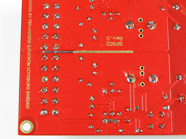
Each halves are isolated from each other and the way to tie them together is to solder the ground planes together, all the way or just a part. It should be better to do is I have done in the picture but it won't hurt I'll guess to solder all the way.
Build two positive regulators
- Do not mount LM337, IC2
- Mount IC3 with a LM317
- Change direction for all diodes
- Change direction for all electrolytic caps
- Change direction for the rectifier bridge
Technical data
| Output voltage: |
+1.2 to +35 V and -1.2 to -35 V or 2 x +1.2 to +35 V Both halves are isolated to each other so it's possible to connect the outputs in series. |
| Max current: | Determined by the output voltage. Limiting factor is max 1 W power dissipation of the regulators and 1 watt in load per side. For 15 volts out typical current is 70 mA. |
| Other data: | See the datasheet for the LM317 and LM337. |
| Dimensions: | 76.2 (3.0") x 118.1 (4.65") mm |


