The schematic
The circuit
The rectifier bridge is built by four ultra fast recovery diodes plus four heavy duty polypropulene capacitors PHE450 from the famous swedish company EVOX-RIFA. As an option you can choose to have only a capacitor or a capacitor plus a resistor. The values can go from 1-100 nF and 1-100 ohms and to really determine the exact value you must have spectrum analyzer which no DIY'er have I suppose. 1 ohms and 100 nF is a good start I think. You don't have to use the type of capacitor I have suggested. The pcb has holes for almost any type with pin spacing, 0.2, 0.25, 0.3, 0.35, 0.4, 0.45, 0.5, 0.55 and 0.6"inch, from 5 to 15 mm.
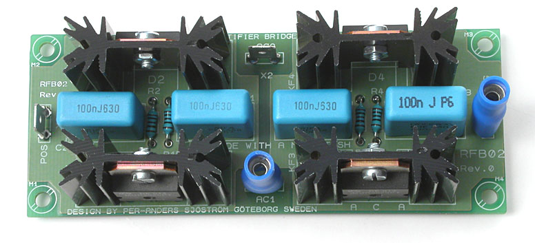
Top view of the RFB-02.
Virtually any diode, especially if they have TO247 or TO218 case, fits. You can even use regular round ones. MUR3020 (200V, 35 ns) and MUR3060 (600V, 60 ns), MUR820 (200V, 25 ns) and MUR860 (600V, 45 ns IR, 25 ns ON-Semi) seem to be good choices.
Two manufactures of diodes can be found here:
If you plan to use this bridge in a preamp, you won't probably need any heatsinks. If you plan use this bridge in a heavy duty application you must use heat compound between the diode and the heatsink. This compound is usually white and I recommend you to use a silicone free product because the silicone has the tendency to creep all over the place and collect dust.
You'll connect the bridge with ordinary lug connectors. Then you can use cables with an area of 6-10 square millimeters.
As a general rule for this project, use any component, audiophilic or not. As long as it's fits for the application it's OK to use it.
