SSR-02 The Sjöström Super Regulator, negative version

Click on the picture to get a larger view.
Some background can be found in my JSR-01 project and in the SSR01 project.
This design is based on my SSR-01 project and the goal was to make the pcb with hole mounted parts as small and versatile as possible.
Interesting features
- 4-layer pcb with 70 um (2 oz.) copper.
- Power traces 140 um!
- Gold pads.
- Extremely low noise.
- Extremely low output impedance in the audioband.
- Small size.
- Easy to change voltage, also to negative voltage but this particular design (pcb) requires two different pcb's, one for positive voltages and one for negative.
- Well-known and well-tested in serious and demanding applications.
- Option for TO92 or SOT23 transistors for the small signal transistors.
- Option for DIL08 or SO08 opamp.
- LM431 (and similar) reference or devices like LM329. The pcb has a universal footprint.
- Trimming options for both the reference and the feedback. Room for extra resistors and trimpots.
- One output with sense inputs.
- All resistors 10 mm so it is possible to use a cut and bending machine for those parts.
- Option for using higher voltage than the max supply voltage for the opamp.
Information
The SSR-02 is identical to the SSR01, the positive version, when it comes to circuit design and the pcb layout. Please read more about the SSR02 here.
Assembly instructions
This design is very easy to build. . You can solder the parts in the order you'll like but it may be practical to start with all low parts such as resistors and then take higher parts.
Start with all low parts except for the output power amp and the opamp.
- Opamp if it's a SMD type. It's hard to solder if you have any parts around the opamp.
- Resistors, jumpers
- Zener diodes
- Plastic capacitors
- Transistors, voltage reference. Fat outline = LM431. Thin outline = LM329 or other 2-pin devices.
- LED
- Trim pot (if you use it)
- Capacitors, elelctrolytic
- Regulator, power transistor
Heat demanding
The pcb has four layers and therefore it requires much more heat than regular two-layer pcb. Ecpecially the ground connections are heat demanding. Use a 50 watts (at least) temperature controlled soldering iron and warm the pad so it really melts and tin flows to the component side. As you can see in my pictures I haven't succeeded to make 100% perfect solder joints and especially hard are the ground connections. If you check the R3, here I should have burned with the soldering iron a lot more. You can warm up the pcb with a hot air gun if you have a weak soldering iron. This will make a lot better result. It's not crucial for the function to have tin through the hole since they are plated.
Besides from these instructions the regulator is pretty easy to build but pay attention how you should mount all polarized parts. See pictures below and also the pdf file. In the pdf file I have made placement pictures with extra clear markings for each part. Print it and have it beside you when you solder.
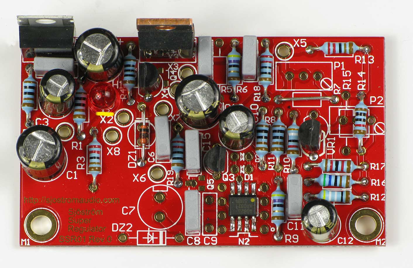
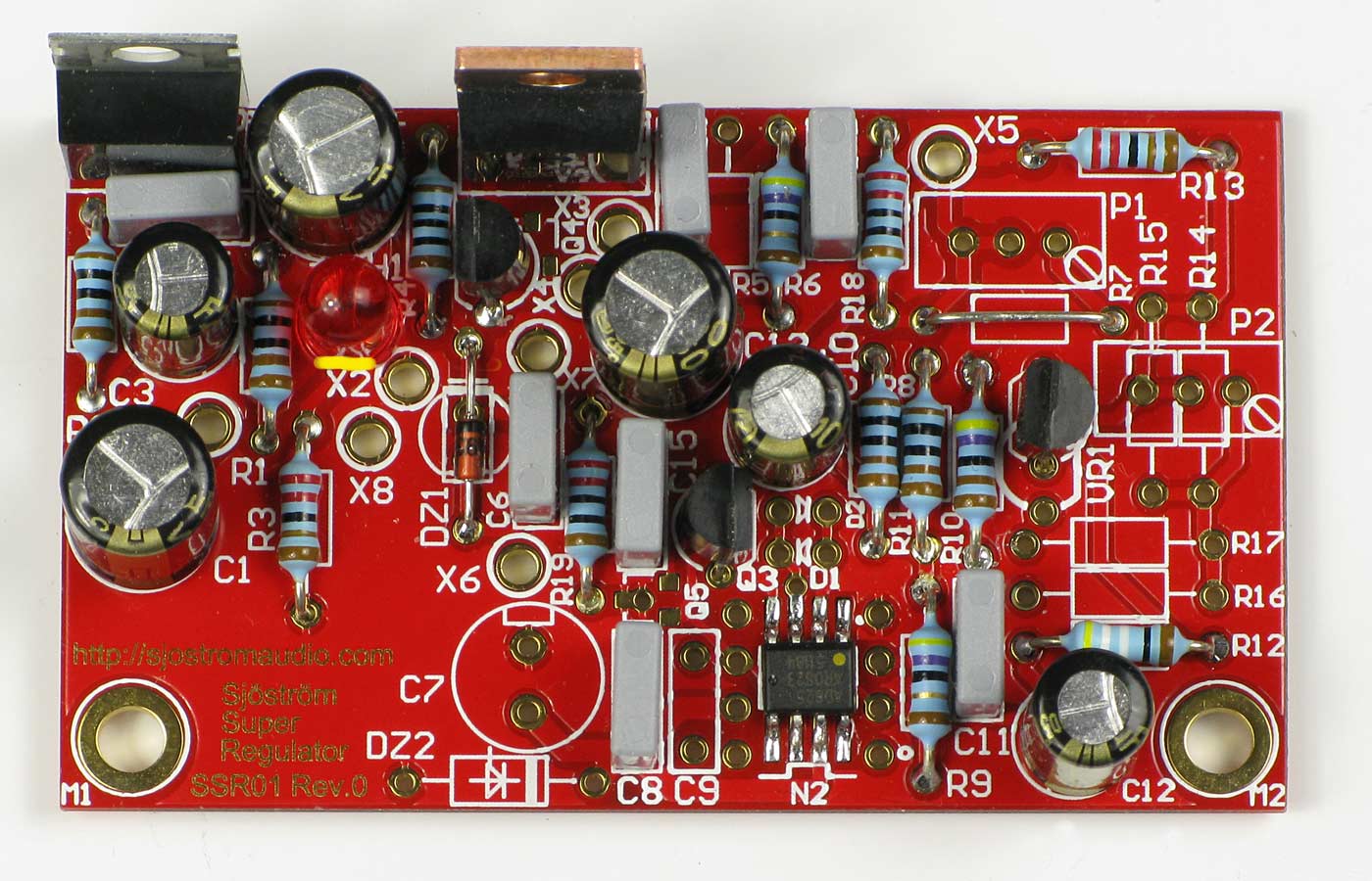
5 V with LM431
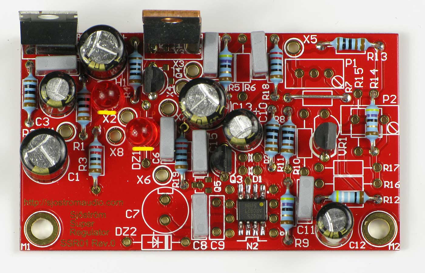
Click on the picture to get a larger view.
The picture shows the SSR01 and the difference between SSR01 and SSR02 is all electrolytic caps (turned 180 deg), LED's, diodes, zeners (turned 180 deg). Otherwise the mounted will be the same. Please check carefully the parts placement documention and the silkscreen print in the pcb. The yellow stripe is cathode or the short leg of the LED. Notice also the yellow dot at the opamp.
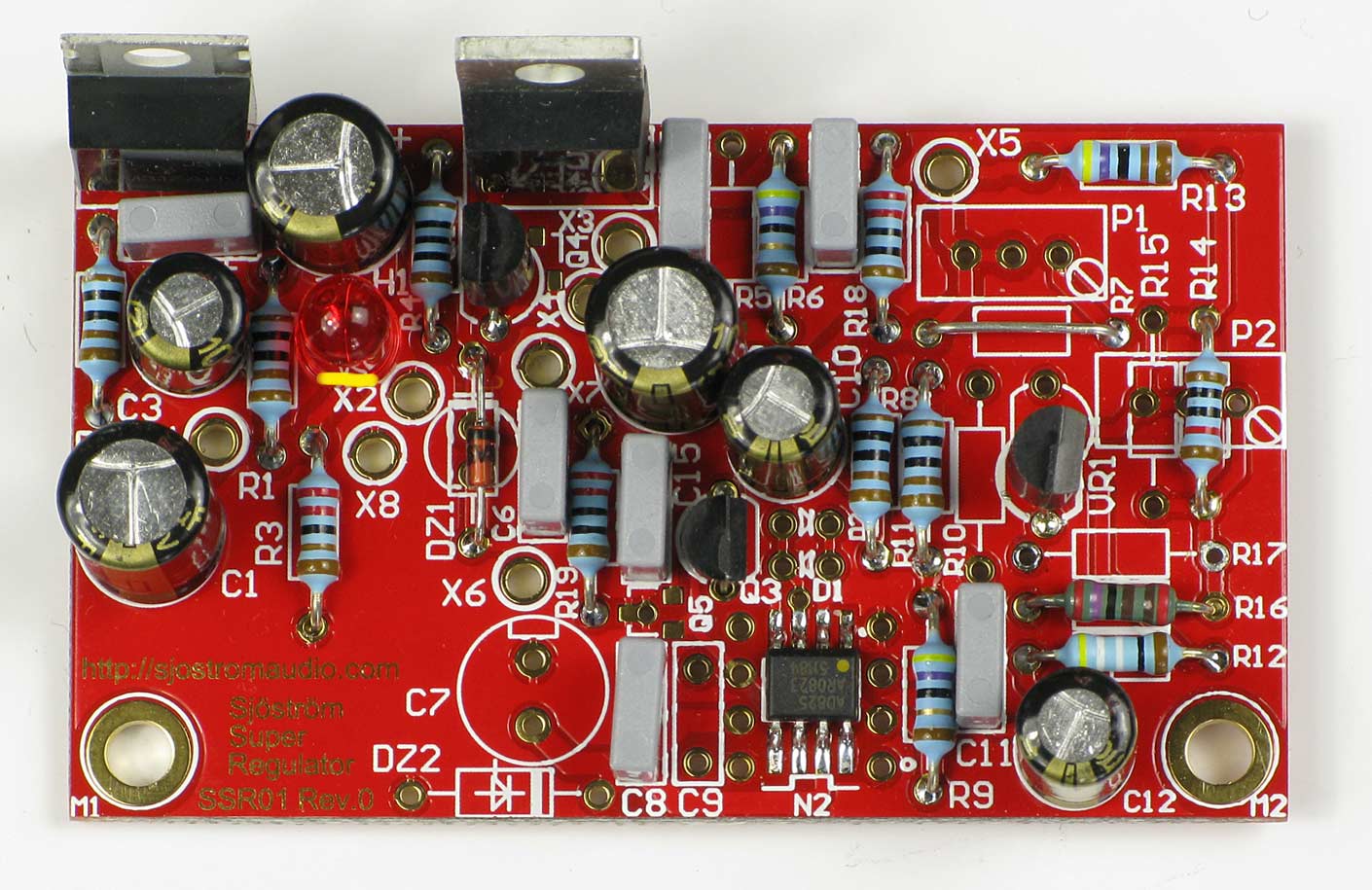
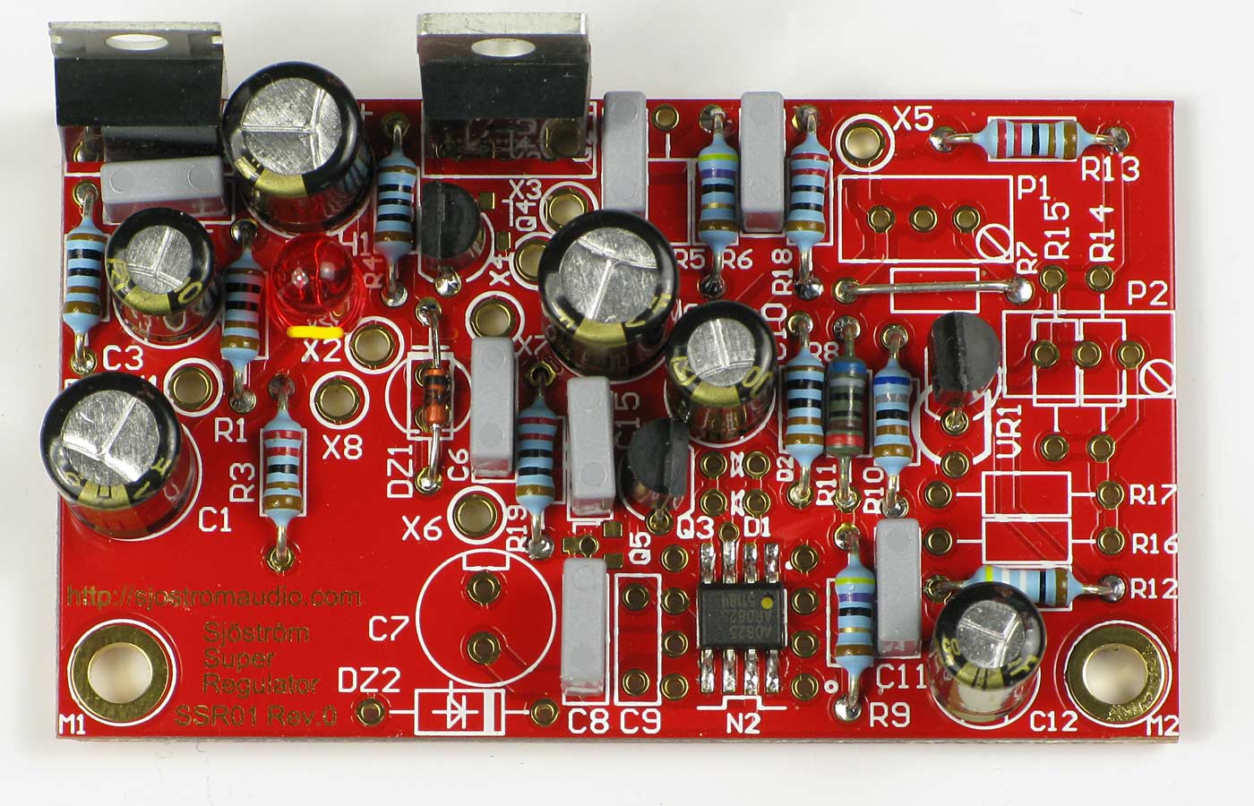
9 V with LM431
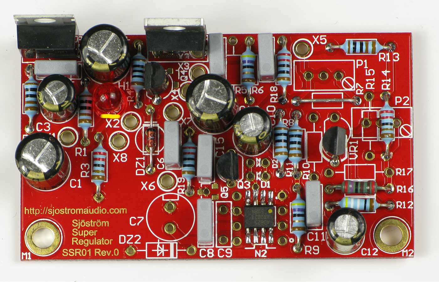
Click on the picture to get a larger view.
The picture shows the SSR01 and the difference between SSR01 and SSR02 is all electrolytic caps (turned 180 deg), LED's, diodes, zeners (turned 180 deg). Otherwise the mounted will be the same. Please check carefully the parts placement documention and the silkscreen print in the pcb. The yellow stripe is cathode or the short leg of the LED. Notice also the yellow dot at the opamp.
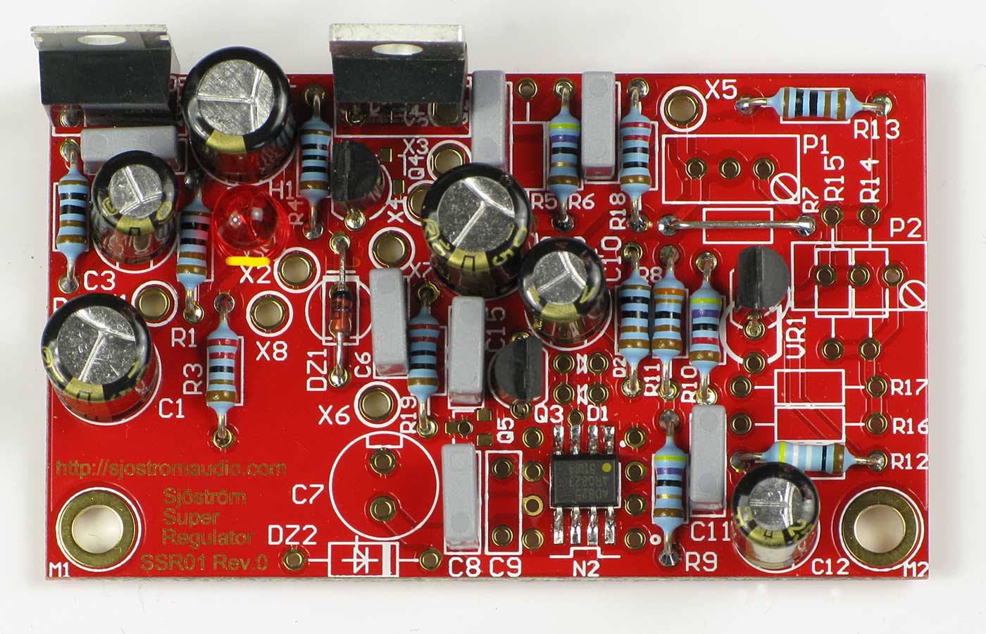
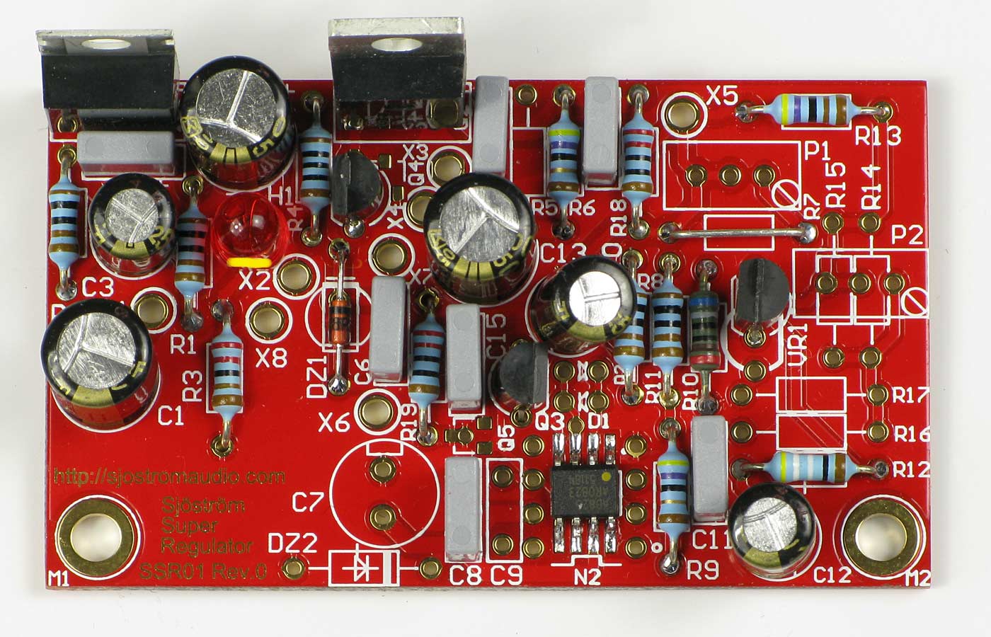
12 V with LM431
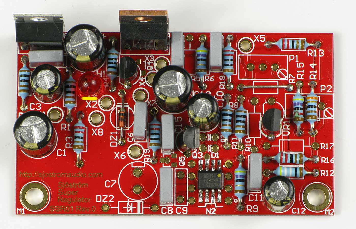
Click on the picture to get a larger view.
The picture shows the SSR01 and the difference between SSR01 and SSR02 is all electrolytic caps (turned 180 deg), LED's, diodes, zeners (turned 180 deg). Otherwise the mounted will be the same. Please check carefully the parts placement documention and the silkscreen print in the pcb. The yellow stripe is cathode or the short leg of the LED. Notice also the yellow dot at the opamp.
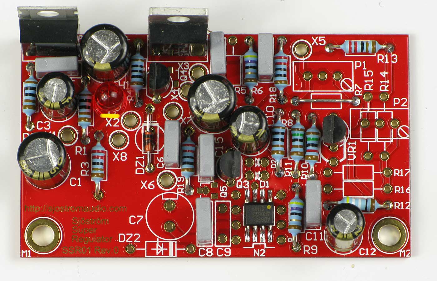
15 V with LM431
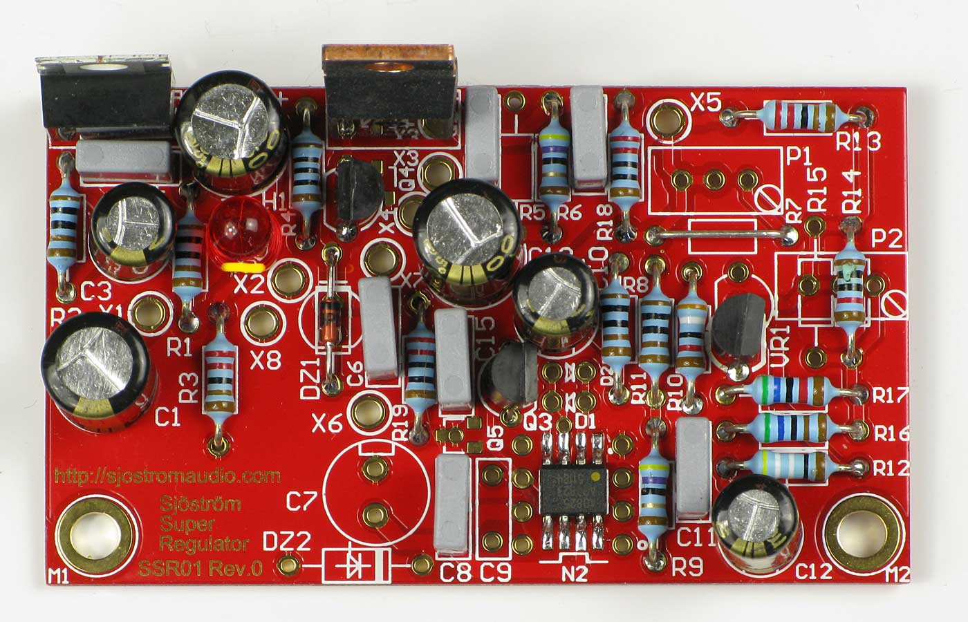
Click on the picture to get a larger view.
The picture shows the SSR01 and the difference between SSR01 and SSR02 is all electrolytic caps (turned 180 deg), LED's, diodes, zeners (turned 180 deg). Otherwise the mounted will be the same. Please check carefully the parts placement documention and the silkscreen print in the pcb. The yellow stripe is cathode or the short leg of the LED. Notice also the yellow dot at the opamp.
18 V with LM431
Click on the picture to get a larger view.
The picture shows the SSR01 and the difference between SSR01 and SSR02 is all electrolytic caps (turned 180 deg), LED's, diodes, zeners (turned 180 deg). Otherwise the mounted will be the same. Please check carefully the parts placement documention and the silkscreen print in the pcb. The yellow stripe is cathode or the short leg of the LED. Notice also the yellow dot at the opamp.
24 V with LM431
Click on the picture to get a larger view.
The picture shows the SSR01 and the difference between SSR01 and SSR02 is all electrolytic caps (turned 180 deg), LED's, diodes, zeners (turned 180 deg). Otherwise the mounted will be the same. Please check carefully the parts placement documention and the silkscreen print in the pcb. The yellow stripe is cathode or the short leg of the LED. Notice also the yellow dot at the opamp.
9 V with LM329
Click on the picture to get a larger view.
The picture shows the SSR01 and the difference between SSR01 and SSR02 is all electrolytic caps (turned 180 deg), LED's, diodes, zeners (turned 180 deg). Otherwise the mounted will be the same. Please check carefully the parts placement documention and the silkscreen print in the pcb. The yellow stripe is cathode or the short leg of the LED. Notice also the yellow dot at the opamp. The LM329, VR1 is placed in the alternative position.
12 V with LM329
Click on the picture to get a larger view.
The picture shows the SSR01 and the difference between SSR01 and SSR02 is all electrolytic caps (turned 180 deg), LED's, diodes, zeners (turned 180 deg). Otherwise the mounted will be the same. Please check carefully the parts placement documention and the silkscreen print in the pcb. The yellow stripe is cathode or the short leg of the LED. Notice also the yellow dot at the opamp. The LM329, VR1 is placed in the alternative position.
15 V with LM329
Click on the picture to get a larger view.
The picture shows the SSR01 and the difference between SSR01 and SSR02 is all electrolytic caps (turned 180 deg), LED's, diodes, zeners (turned 180 deg). Otherwise the mounted will be the same. Please check carefully the parts placement documention and the silkscreen print in the pcb. The yellow stripe is cathode or the short leg of the LED. Notice also the yellow dot at the opamp. The LM329, VR1 is placed in the alternative position.
18 V with LM329
Click on the picture to get a larger view.
The picture shows the SSR01 and the difference between SSR01 and SSR02 is all electrolytic caps (turned 180 deg), LED's, diodes, zeners (turned 180 deg). Otherwise the mounted will be the same. Please check carefully the parts placement documention and the silkscreen print in the pcb. The yellow stripe is cathode or the short leg of the LED. Notice also the yellow dot at the opamp. The LM329, VR1 is placed in the alternative position.
24 V with LM329
Click on the picture to get a larger view.
The picture shows the SSR01 and the difference between SSR01 and SSR02 is all electrolytic caps (turned 180 deg), LED's, diodes, zeners (turned 180 deg). Otherwise the mounted will be the same. Please check carefully the parts placement documention and the silkscreen print in the pcb. The yellow stripe is cathode or the short leg of the LED. Notice also the yellow dot at the opamp. The LM329, VR1 is placed in the alternative position.
Test
If you don't plan to use the "sense" function, put a tin blob on the solder side at J1 and J2 (see the schematics also).
- Use a regulated power supply and set the current limit to 50-100 mA or something low.
- Connected a voltmeter at the output.
- Turn up the voltage slowly and observe the output and the current consumption. When the LED H1 starts to shine you should have a stable output voltage.
- Add a load to check is the voltage still is stable including some warm-up of the opamp and the voltage reference (a few millivolts).
If you have the preregulator LM337 installed the output voltage should be stable with 4-5 volts more in than set output voltage.
Technical data
| Operating voltage: | Max 50 V, less current at high voltage in. Min 4 volts more than output voltage. |
| Output voltage: | 5-40 V, down to 3 volts is possible. |
| Hum and noise at full output current: | Down to 0.9 µV or below depending of component choices |
| Max current: | Approx 1 A peak |
| Max continuous current: | Approx 1 A depending of ambient temperature and mounting (cooling). |
| Dimensions: | 66,0 (2.6") x 38,1 (1.5") mm |
Measurements are done by Jack Walton, jackinj, with an Audio Precision measurement system.
| Used parts | LM329, AD825 | LM329, AD797 | LM329, LT1028 |
| No filter: | 15.14 µV | 5.67 µV | 6.95 µV |
| A-Weighted: | 2.38 µV | 1.03 µV | 1.00 µV |
| CCIR-486: | 6.40 µV | 2.04 µV | 2.02 µV |
| CCIR-2K(Avg): | 3.03 µV | 0.941 µV | 0.921 µV |
| 22-22K: | 3.52 uV | 2.37 uV | 1.70 uV |
