Build directions

It's really easy to build this bridge.
Start with mounting caps and the resistors. Just solder them in. It's good to start with them because they are a bit hard to mount when the diodes are mounted.
Mount connectors.
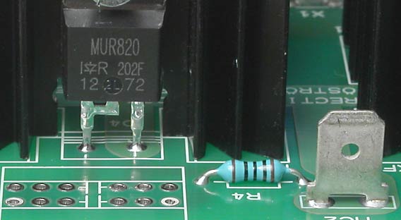
Continue with mounting the diodes on the heatsinks. You don't need any insulation because the heatsinks aren't connected to anything but KF3 and KF4 must be mounted 1 mm or so above the pcb. Just press in a cardboard between the heatsink the pcb when you solder. KF1 and KF2 is connected to cathode which the groundplane under those also is. Solder the heatsink with a very small drop of tin, just so it won't fall off. Then solder the diode. When the whole bridge is finished and tested you may solder the heatsinks a little bit better. This is just a precaution if you want to remove the heatsinks of some reason before you are completely finished. Once you have soldered them in they will be impossible to remove without damaging the pcb.
Soldering
The picture shows RFB01 but the problem is the same with RFB02. Some parts are demanding in terms of heat. The pcb has thick copper which cools good. Therefore you must "fire up" some pads. Those pads with wide traces demands lot's of heat. If you have a temperature controlled soldering iron turn up the temperature to max, maybe 450 deg C! Stop warming when the tin has start to flow up on the component side. See the picture above. Note also that the lug had a thick oxide layer. The soldering joint isn't perfect. The tin hasn't wet the surface of the lug but still, the quality is fair.
