Build +12 V and -12 V power supply
+12 V and -12 V
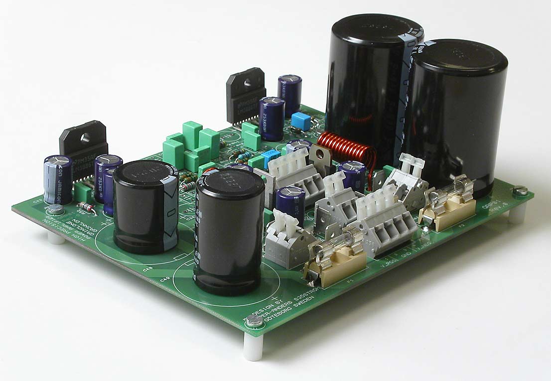
Start with the voltage regulators for the opamps.
Connectors X1 or A1-A4, F1, F2, C46 - C57, R41, R42, IC9, IC10. Notice how the electrolytic caps should be turned. Note the stripes for indicating negative pole on the capacitors and see also the corresponding marking in the pcb. I have also + signs in the pcb but those can sometimes be rather unclear.
Connectors X2, X3 or A5, X4 (please note that I have forgotten the spade connectors for incoming ground), X5 or A6.
Apply voltage, +20-42 V DC and -20 to 42 V DC. Check that you have +12 V +-5% at pin 8, IC2 and -12 V +-5% at pin 4, IC2 or other suitable point.
If you don't get 12 V you may load the regulators a bit. Load them with 1-10 kohms. Certain brands of regulators demands a minimum load i order to regulate.
Disconnect the voltage and wait until you will have less than 1 V at the big caps. If you can't wait and also have big 10000 uF caps, discharge with a 3.3 kohms /0.6 W resistor or a 100 ohms, 4 W. USE NOT A WIRE. YOU CAN DAMAGE THE CAPS IF THEY ARE DISCHARGED TOO BRUTALLY.
