Circuit description
The PA03 can be considered as universal as possible both from wiring and from mechanical construction points of view. You only have to add a power supply switch, power supply transformer, input and output terminals.
Applications
The module can be used in various ways:
- a power amplifier in small active two-way boxes
- a small stereo power amplifier.
- when using several modules you can build an active three-way box (120W/60W/60W),
- stereo power amplifier 2 x 120 W, 2 x 220 W
- various multi-channel amplifiers for home theater applications.
Connecting accessories
The board has a stabilized DC voltage ±12 V (±15 V), which is available in the input connector of the PA03 Module. Various auxiliary circuits can be powered (active crossover, which is considered as the next step of my developments, preamplifier etc.). The mute function is also available in the input connector of the PA03 module.
Input amplifier
The input amplifier (OA1, 2) is a balanced amplifier and it enables connection of both balanced and unbalanced signal sources. The signal source output phase can be chosen with the jumper to appropriate pins of JP2 and JP3 connectors. If the jumper is inserted at the “+” signed pin, the amplifier inverts the phase. If the jumper is connected to the “–“ signed pin, the phase is not inverted. The signal must be connected to the non short-circuited pin.
Balanced mode
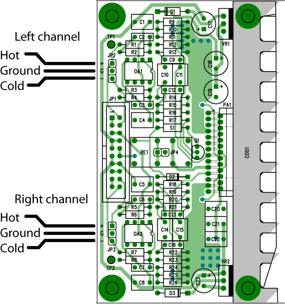
Click on the picture to get a larger view. Inputs connected for balanced mode.
You can connect in two ways, either use the header connector J1 or using J2 and JP3. Check the schematics how the signals are connected in JP1.
If you want to use balanced input signals you must make sure that the resistors around OA1,OA2 is pretty well matched in order to get good common mode rejection ratio. You only have to match each opamp at the time.
These resistors should have the same values
R1, R3
R2, R4
R5, R7
R6, R8
The absolute value isn't critical, just that they are alike. Plain 1% metal film resistors have 0.3% tolerance in real life so the necessity to match in not very high. This match could be done with any 3.5 digit DVM. 0.1% tolerance is possible. You could also by better resistors, i.e 0.1% but it's hardly worth it.
Non-inverted mode
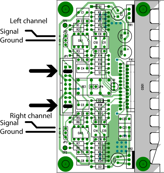
Click on the picture to get a larger view. Inputs connected for non-inverting mode.
You can connect in two ways, either use the header connector J1 or using J2 and JP3. Check the schematics how the signals are connected in JP1.
The non-inverted mode (jumper inserted to the “–“ signed pin) is recommended for the signal input of the PA03 as a stereo power amplifier.
Inverted mode

Click on the picture to get a larger view. Inputs connected for inverting mode.
You can connect in two ways, either use the header connector J1 or using J2 and JP3. Check the schematics how the signals are connected in JP1.
The inverted mode (jumper inserted to the “+“ signed pin) is recommended for the signal input of the PA 03 as a stereo power amplifier and if you of some reason prefer inverting input buffers. One possible advantage is theoretically ten times lower distortion from the input buffer. The disadvantage is lower input impedance.
Bridged mode
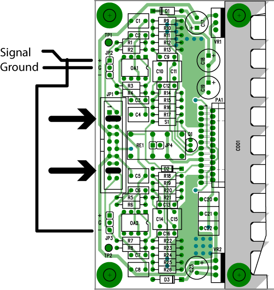
Click on the picture to get a larger view. Inputs connected for bridged mode.
This mode is used when you'll have 8 ohms load and want in theory 4 times the power. In real life you'll get less. The left channel goes in non-inverting mode and the right in inverting mode.
As mentioned before about matching, here it's also important but R1-R8, should be alike if possible. R14 and R12, R15 and R20, R16 and R19, R9-R11 and R24-R26. For the last ones it's only important to get the paralleled sum alike. The reason for this matching is for achieving a symmetrical (balanced) output so the LM4780 won't get some much offset creating excessive and unnecessary heat.
One single speaker is connected between the outputs and is therefore not grounded. The speaker must be left floating and not be connected to anything else.
Paralleled mode
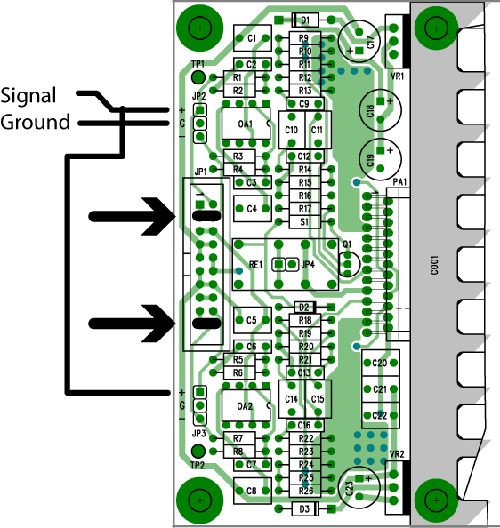
Click on the picture to get a larger view. Inputs connected for bridged mode.
This mode is used when you'll have 2 ohms load and want in theory twice the power. In real life you'll get less. Both channels goes in non-inverting mode (or inverting if you'll prefer that).
As mentioned before about matching, here it's also important but R1-R8, should be alike if possible. R14 and R12, R15 and R20, R16 and R19, R9-R11 and R24-R26. For the last ones it's only important to get the paralleled sum alike. The reason for this matching is for achieving an identical output on both channels so the LM4780 won't get some much offset creating excessive and unnecessary heat.
Supply voltage of the input buffer
The supply voltage of input amplifiers is chosen to ±12 V, because some of up-to-date operational amplifiers are constructed for this lower value of power supply voltage. Max voltage is 13.5 volts for them and ±15 V is too much. Almost any opamp will work with ±12 V. This isn't any drawback really since the LM4780 only want 1-2 V before it's choked. If you of some reason want to use 15 V voltage regulators, please do so but you must replace the resistor S1,(2R2) with another one with the value of 680R, because the relay R1 is designed for 24 V DC. TheOPA134 is recommended as an input amplifier but you can try to use different types (OPA627,AD8065, AD8610 and similar ones).
Power amplifier
Power amplifier operates in the non-inverted amplification circuit. The feedback loop is divided into DC and AC parts to reach an excellent signal-to-noise ratio. There is a similar value of total impedance on both amplifier inputs and this feature makes reaching a low distortion possible. Low current noise is ensured when using a high value of the R12 and R15 resistors. Low voltage noise requires the values of input and feedback impedance's to be the lowest as possible, that is why the values of the R9, R10, R11, R14 and R14 resistors are low. The R9, R10 and R11resistors are connected in a parallel way to minimize thermal distortion. The capacitor C 11/C14ensures separation of DC and AC feedback loops.
Active speaker
If you use this module in an active box, the value of the C15 for bass section should be 47μF, for treble section 1μF (the bottom cut-off frequency is approx. 40 Hz with the value of C15 = 1 μF). Both channels should have the value of C11/C15 = 47 μF in you use the PA 03 module as standard stereo power amplifier. The parallel amplifier application can be used if the load impedance is too low (2 Ω) or if you want to use two PA 03 modules in bridged amplifier application to obtain a high output level (220W/4Ω). In both cases the PA 3 module inputs are parallel connected. In the parallel amplifier application the outputs are parallel connected and the load is connected between the outputs and the earth.
Bridged connection
If you would like to connect two PA03 modules for bridged amplifier application, you must connect the inputs of one module inputs to the inverted mode. All four amplifier inputs then must be connected parallel. The load is connected between the parallel connected outputs of both modules.
Parallel connection
The parallel amplifier application requires a small external output resistor, in our case 0,1Ω (ten times 1 Ω connected parallel). The amplifier is able to supply a heavy capacitive loading. I have tested the complex load consisting of an 8 Ω resistor and a parallel connected capacitor 100 pF to 5 μF with excellent results.
Power supply
The power supply is wired in a simple way, it means one bridge rectifier and two filter capacitors. Snap-in capacitors will fit from 15000 μF to 22000 μF /40V (diam. 35 mm, height 35 to 50 mm, manufacturer Kendeil, Chemicon, Elna, Rubycon, Panasonic, Jamicon and many more) and bridge rectifiers KBU8 or KBU12 are recommended. Voltage rating should be 200 V or more such as KBU8D.
Transformer
The mains transformer should be 200 VA (160 VA to 300 VA) for each PA03 module. If you want to use a common mains transformer for several PA03 modules, a separate secondary winding for each module is recommended to ensure minimum cross-talks between the modules and problems with ground loops.
Supply voltage
The PA03 module can be operated within DC supply range from ± 20 VDC to± 40 VDC (see alsoLM4780 datasheet). The main voltage supply tolerance must be also considered when the main transformer is being designed. The highest allowed DC voltage is ± 42 VDC on the filter capacitors. Both toroidal and EI transformer can be used as main transformer. I recommend using a toroidal one. Recommended transformer voltage is 2 x 15 to 2 x 24 VAC. Avoid more than 24 VAC since the power increase in dB's will be very small but the LM4780 will get much hotter to no use.
Mute function
Using the mute function the PA03 module can be switched to a low power consumption mode, normally called as "Stand by". You do not have to switch the main switch off. A wide range of applications can be found, for example in subwoofer amplifiers or active boxes. The mute function can be activated by the relay RE 1. If the mute pin on the input connector is connected to the earth (through a mechanical contact or PNP transistor). In case you do not use this function, the relay RE 1 need not be mounted, you must use the pins JP4 with jumper. The mute function is now deactivated.
Protection and additional circuits
Overtemperature
Protection circuits are integrated in the LM4780 power amplifier. These circuits contain short circuit protection (against ground and both power supply voltages), overloading protection and thermal overload protection. If the LM4780 power amplifier is thermally overloaded, the output power is reduced or even reduced to zero. After the heatsink temperature has gone down, the amplifier starts with the normal operation.
DC output protection
Most users rely on internal protection circuits but I've added a separate protection against DC voltage on the amplifier output using an output relay with a protection circuit.
Delayed on, silent power off
Delayed load connection after switching on, the amplifier and the immediate load disconnection after switching off the amplifier is also integrated, with the help of CMOS 4020 counter. This counter is set to zero after connecting an AC supply voltage through the on state of the Q8transistor. After that pulses formed by the squaring unit Q7 from the mains frequency are counted. When the pre-set amount of pulses is reached, the counter output (Q9) is reversed and with the help of the transistor Q6 the input of squaring unit is blocked and the counter is frozen in the "H" state. After disconnecting AC supply voltage the capacitor C 35 is discharged through the B-E junction of the transistor Q7. This transistor will be closed, counter state is reversed into "L" and is prepared for a new cycle. The counter state influences the switching transistor Q5, which switches the output relays. The output relays coils are connected in series and supplied from the DC voltage. Their coils are connected after safety fuses of power amplifier. If one of them is interrupted, both relays are immediately disconnected. Coil voltage of the used relays is 24 V DC. Two of them are connected in series and have a nominal voltage of 48 V DC. Because the amplifier power supply is higher, the necessary matching is done with the help of a zener diode (for DC voltage ±35 V a 18 V zener diode should be used). In the same way the voltage stress of stabilizers for input amplifiers is restricted by the use of Zener diode (in this case 6.8 V). Transistor Q5, which switches the output relays, is driven by the transistor Q4. The output of DC voltage detector is also connected to the transistor Q4 base. The AC voltage on both amplifier outputs is suppressed by the RC filter (R61, C31, 33 and R60, C32, 34) and the DC detector is not active. If there is a DC voltage higher then ±3 V on one or both outputs, transistors Q2 andQ3 will open and make a short-circuit between the basis of the transistor Q4 and negative supply line, the transistor Q4 will be closed and both relays will disconnect the load. This type of protection is well-known and proven.
Heatsink mounting
LM4780 cooling surface is connected to the negative power supply line. The heatsink can be mounted directly to the LM4780 amplifier if there is no connection between the heatsink and ground (if you use the PA03 module as a stereo power amplifier in a separate box). In this case you can achieve the best possible cooling of the amplifier. In case you want to use more PA03 modules connected to the common heatsink, you must use a proper insulating underlay (SARCON, SILPAD800) with a low thermal resistance.
7812 cooling surface is connected to the ground and it must be insulated.
7912 cooling surface is connected to a negative potential, the same as the input of the regulator and it must be insulated.
Main transformer and load connection
AC voltage and load can be connected to the PC board with the use of WAGO terminals, 255 or 256 lines, or screw terminals. You can also solder the wires into the PC board directly.
Relays
Any suitable relay having adequate terminals layout can be used for mute control and load connection. The switching capacity of the relays for load connection should be at least of 5 A, 10 or 16 A is recommended. They will never switch off with full load. You can also use 2-pole relays rated 5 A per contact. A such relay will have their contacts in parallel. The contact material should be hardsilver. Avoid AgCdO because of the bad signal properties at low currents, bad for the nature also (Cadmium). Choose the big brands such as Finder, Elesta, Feme, Schrack,Omron, Takamisawa etc.
Ground connection of several PA03 modules
If you use only one PA03 module in your project, you do not have to connect this module to the ground, but you can do it. The best way is to try out solution. There is a hole for threaded distance spacer between the fuses on the PA03 PC board. You can use a metal spacer for connection to the ground or a nylon one and the PA 03 module ground will not be connected to the chassis. If you use more PA03 modules with a common heat sink, you can use this heat sink for grounding. There are connection points marked with “G” on the PC board. You can also use wires connected to this points for ground connection.
